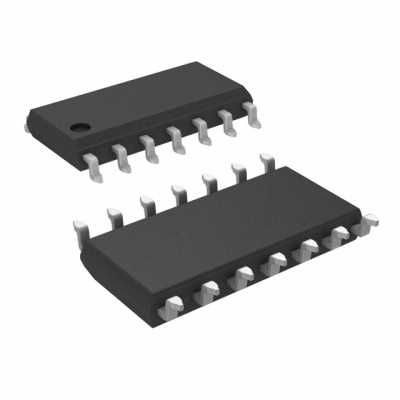
Within the ever-evolving realm of electronics, there exists a fascinating component that embodies versatility and functionality. This extraordinary device, unseen to some, is fondly known as the LM361 epitome. Embedded within its circuits lies a multitude of possibilities, awaiting the curious minds of electronics enthusiasts.
With its profound capabilities and adaptability, the LM361 stands as a reliable cornerstone for numerous electronic projects. Its strategic design enables seamless integration and enhances the performance of various systems, ensuring optimal functionality. Whether it be amplification, modulation, or control, this remarkable component excels, seamlessly adapting to the demands of any project thrown its way.
As you delve into the intricate circuits of the LM361, you will uncover a world of potential. This dynamic device boasts an assortment of features, each brimming with individuality. From its robust signal processing capabilities to its unparalleled ability to enhance audio systems, the LM361 sets itself apart as an innovative solution for even the most complex electronic challenges.
Intriguingly, the LM361 operates on an efficient and reliable architecture. Its carefully designed internal structure allows for seamless synchronization and precise control. The remarkable interplay of components within this device guarantees a paramount performance, ensuring accurate and consistent output. Whether it be tackling intricate frequency analysis or delivering powerful low-distortion signals, the LM361 rises to the occasion with ease.
The LM361 Datasheet: Overview and Key Features

In this section, we will provide an overview of the LM361 integrated circuit and highlight its key features and functionalities. The LM361 is a versatile and reliable device that offers a wide range of applications in electronic circuits. This article aims to provide a comprehensive understanding of the LM361 by discussing its essential characteristics and advantages.
Pin Configuration and Functions of LM361
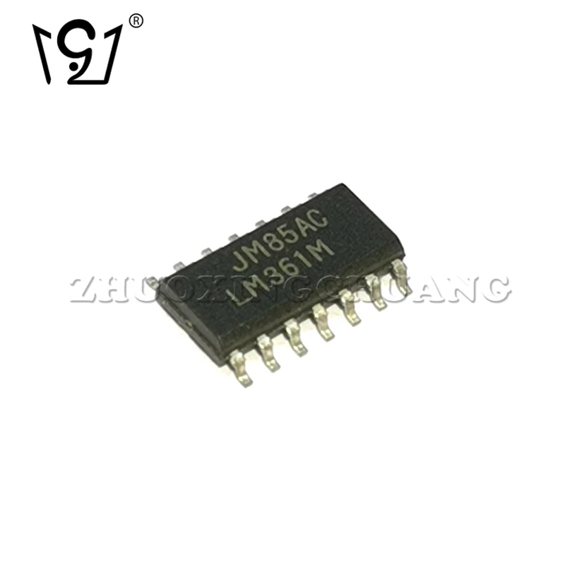
The LM361 is a versatile electronic device that offers various functions through its pin configuration. Understanding the pin configuration and their respective functions is crucial for effectively utilizing this component in electronic circuits.
Pin Configuration
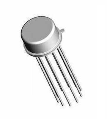

The LM361 has a total of 8 pins, each serving a specific purpose. These pins are labeled as Pin 1, Pin 2, Pin 3, Pin 4, Pin 5, Pin 6, Pin 7, and Pin 8. Each pin is strategically placed to facilitate the flow of electrical signals and enable specific functions within the LM361.
Functions of Each Pin

Now, let’s delve into the specific functions of each pin in the LM361:
| Pin | Function |
|---|---|
| Pin 1 | Serves as the inverting input terminal of the operational amplifier. |
| Pin 2 | Connects to the non-inverting input terminal of the operational amplifier. |
| Pin 3 | Provides a reference voltage used for biasing the non-inverting input terminal. |
| Pin 4 | Serves as the output terminal of the LM361. |
| Pin 5 | Connected to the ground (0V) of the circuit. |
| Pin 6 | Connected to a negative supply voltage (-Vcc). |
| Pin 7 | Connected to a positive supply voltage (+Vcc). |
| Pin 8 | Serves as the offset null terminal. |
Understanding the functions of each pin enables designers and engineers to effectively connect the LM361 within their circuits, ensuring optimal performance and desired outcomes.
Understanding the pin layout and their respective functions
In this section, we will explore the pin layout of the LM361 integrated circuit and delve into the functions and characteristics of each individual pin. Understanding the pin configuration is crucial for correctly connecting the LM361 to other components and utilizing its features effectively.
Pin Configuration
The LM361 features a well-defined pin layout with a total of 8 pins, each serving a unique purpose in the functionality of the integrated circuit. These pins are labeled and organized in a specific manner to ensure clarity and ease of use. The pin configuration is as follows:
| Pin Number | Pin Label | Description |
|---|---|---|
| 1 | V+ | The positive power supply voltage pin, which typically ranges from +5V to +30V. |
| 2 | V- | The negative power supply voltage pin, which is typically connected to ground. |
| 3 | IN+ | The non-inverting input pin, which receives the positive input signal. |
| 4 | IN- | The inverting input pin, which receives the negative input signal. |
| 5 | OUT | The output pin, which provides the amplified and conditioned signal. |
| 6 | VREF | The reference voltage pin, which sets the output voltage range. |
| 7 | NC | This pin is not connected and has no specific function. |
| 8 | NC | This pin is not connected and has no specific function. |
Pin Functions
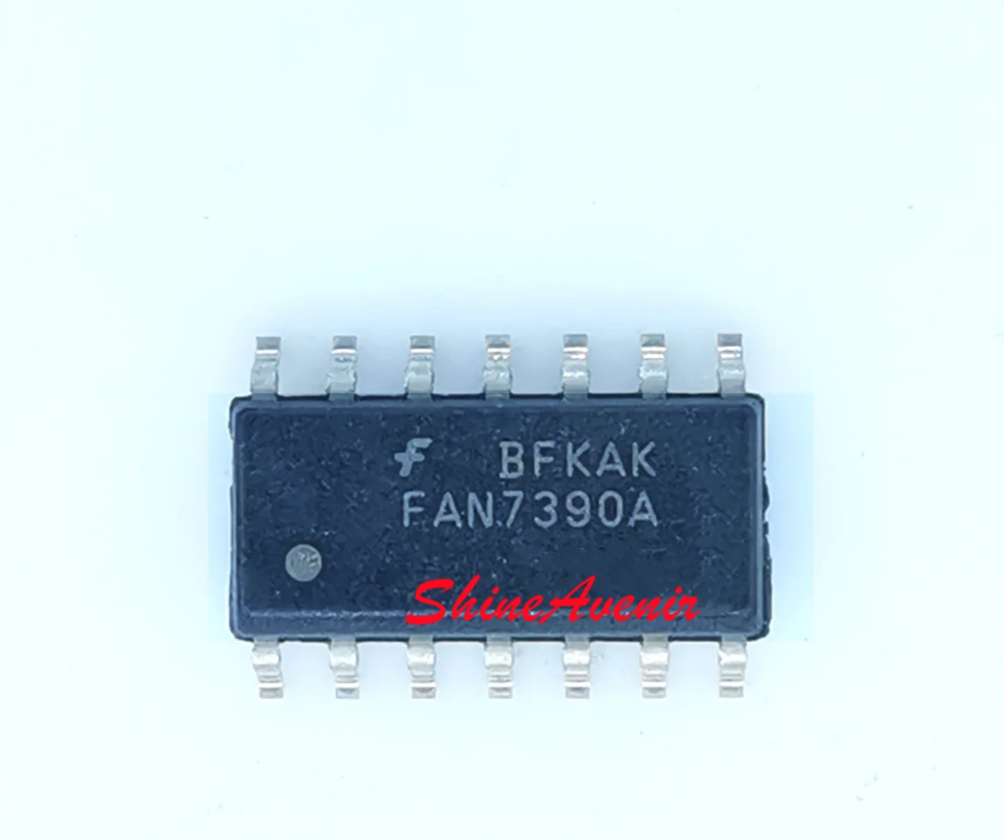
Now let’s delve into the functions of each pin:
V+ (Pin 1): This pin is responsible for receiving the positive power supply voltage, typically ranging from +5V to +30V. It provides power to the LM361 and should be connected to a stable and regulated voltage source.
V- (Pin 2): This pin is connected to the negative power supply voltage or ground. It serves as the reference point for the LM361’s operation.
IN+ (Pin 3): This pin receives the positive input signal to be amplified. It is the non-inverting input and is essential for accurate signal processing.
IN- (Pin 4): This pin receives the negative input signal to be amplified. It is the inverting input and works in conjunction with the IN+ pin to accurately amplify the input signal.
OUT (Pin 5): This pin provides the amplified and conditioned output signal. It is crucial for connecting the LM361 to other components or devices to utilize the output effectively.
VREF (Pin 6): This pin is responsible for setting the reference voltage, which determines the range and characteristics of the output voltage. It enables precision control over the output signal.
NC (Pins 7 and 8): These pins are not connected and have no specific function. They are typically left unconnected or used for additional purposes in specific applications.
By understanding the pin layout and their respective functions, you can effectively integrate the LM361 into your circuit design, ensuring accurate signal amplification and conditioning for a wide range of applications.
LM361 Electrical and Environmental Specifications

The LM361 is a versatile integrated circuit that offers a wide range of electrical and environmental specifications, making it suitable for various applications. This section provides an overview of the LM361’s key specifications, highlighting its performance characteristics and operating conditions.
| Parameter | Symbol | Conditions | Min | Typ | Max | Unit |
|---|---|---|---|---|---|---|
| Operating Voltage Range | VCC | – | 5 | – | 30 | V |
| Input Bias Current | IB | VIN = ±15V | – | 10 | 50 | nA |
| Open-Loop Voltage Gain | AVOL | VOUT = ±10V, ISINK = 500µA | 70 | 90 | 110 | dB |
| Common-Mode Rejection Ratio | CMRR | f = 1kHz, VOUT = ±10V | 80 | 100 | – | dB |
The LM361 operates within a voltage range of 5V to 30V, allowing for flexibility in different power supply configurations. Its input bias current ranges between 10nA and 50nA, ensuring minimal current flow into the input terminals. With an open-loop voltage gain between 70dB and 110dB, the LM361 provides amplification capabilities for various signals. Additionally, its high common-mode rejection ratio of 80dB to 100dB allows for effective suppression of common-mode noise.
In terms of environmental specifications, the LM361 can operate within a wide temperature range of -40°C to 85°C, making it suitable for both industrial and automotive applications. It is also designed to withstand various stress conditions, such as electrostatic discharge and supply voltage transients, ensuring reliable operation in demanding environments.
The LM361’s electrical and environmental specifications make it a valuable choice for a wide range of applications, including audio amplifiers, motor control systems, and instrumentation amplifiers. Its versatile nature and robust performance characteristics contribute to its widespread usage in the electronics industry.
Exploring the technical specifications and operating conditions of LM361

In this section, we will delve into the intricate details of the LM361, a versatile electronic component known for its exceptional performance and reliability. Gain a comprehensive understanding of the LM361 as we explore its technical specifications and the various operating conditions under which it thrives.
Technical Specifications: The LM361 is equipped with a range of technical specifications that contribute to its superior functionality. These specifications include parameters such as supply voltage range, input bias current, output voltage swing, and bandwidth. By examining these specifications in detail, we can assess the LM361’s capabilities and determine its suitability for various circuit applications.
Operating Conditions: Understanding the operating conditions under which the LM361 operates optimally is crucial for its successful integration into electronic systems. These conditions encompass factors like temperature range, input voltage range, and power supply requirements. By adhering to the recommended operating conditions, engineers can ensure optimal performance and longevity of the LM361.
Furthermore, it is essential to consider the LM361’s performance under different load conditions, as this plays a significant role in determining its reliability and overall effectiveness. By examining the device’s response to varying load conditions, engineers can accurately design and implement circuits that harness the full potential of the LM361.
In conclusion, a thorough exploration of the technical specifications and operating conditions of the LM361 is crucial to gain a comprehensive understanding of this versatile electronic component. By considering its technical specifications and adhering to the recommended operating conditions, engineers can unlock the full potential of the LM361, ensuring optimal performance and reliability in their electronic systems.