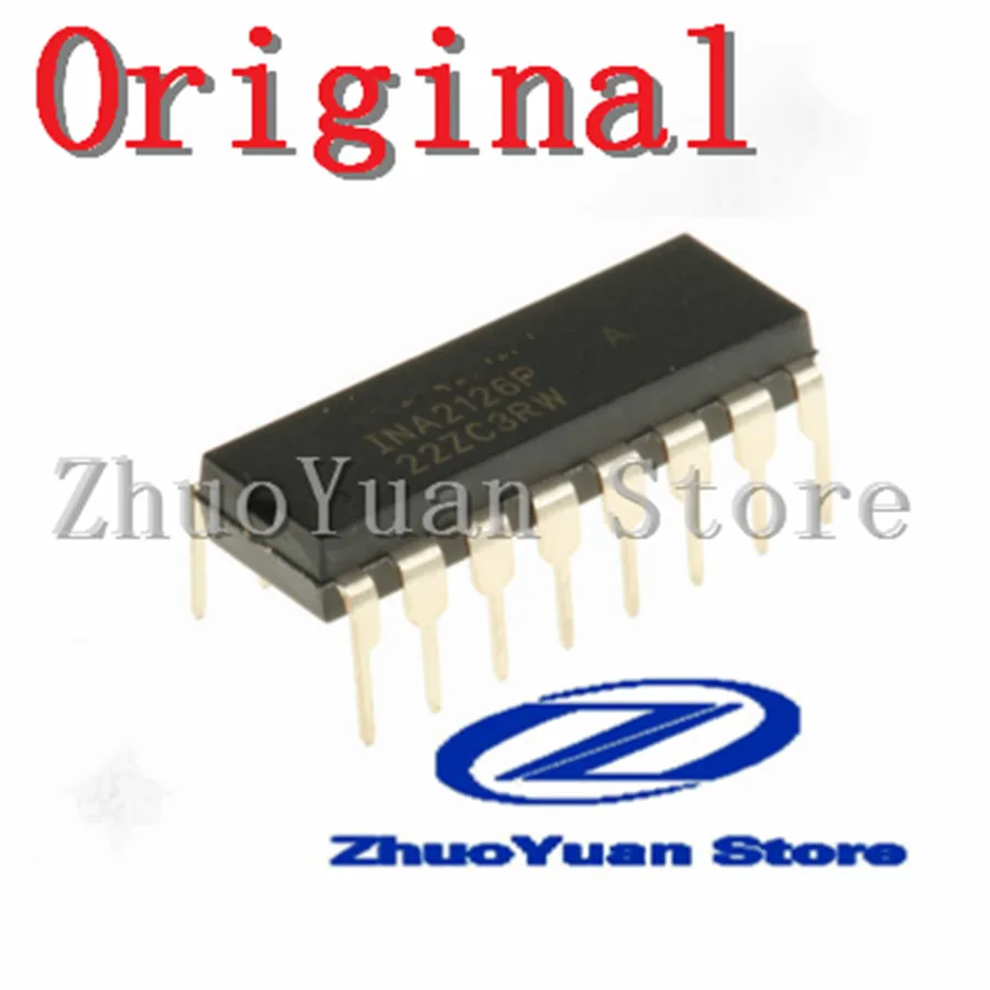
In the realm of electronic components, there exist numerous cutting-edge microchips that power the functionality and performance of a wide range of devices. One such remarkable microchip is the Ina2126p, a powerhouse renowned for its exceptional capabilities and versatility. In this article, we delve into the intricacies of this remarkable innovation, delving into its features, applications, and advantages.
Designed with utmost precision and engineering excellence, the Ina2126p is a revolutionary microchip that exemplifies the epitome of technological advancement. Equipped with a myriad of high-performance components, this microchip sets itself apart in the competitive landscape, catering to the mounting demands of modern electronic applications. Offering an unparalleled level of efficiency and reliability, the Ina2126p serves as a cornerstone for countless electronic devices across diverse industries.
Unveiling its diverse range of applications, the Ina2126p’s potential is truly astonishing. Its flexible design and seamless compatibility make it an indispensable component in a vast array of electronic systems. From precision measurement tools and medical devices to automotive applications and audio equipment, the Ina2126p seamlessly integrates into diverse projects, unleashing its limitless potential for innovation.
Moreover, the Ina2126p’s unique combination of intelligent sensing capabilities and high-speed digital signal processing allows for unparalleled accuracy in data acquisition. With its ability to effortlessly measure and interpret crucial parameters, this microchip empowers engineers and designers to achieve unprecedented levels of precision and performance in their projects.
Featuring Key Specifications and Applications
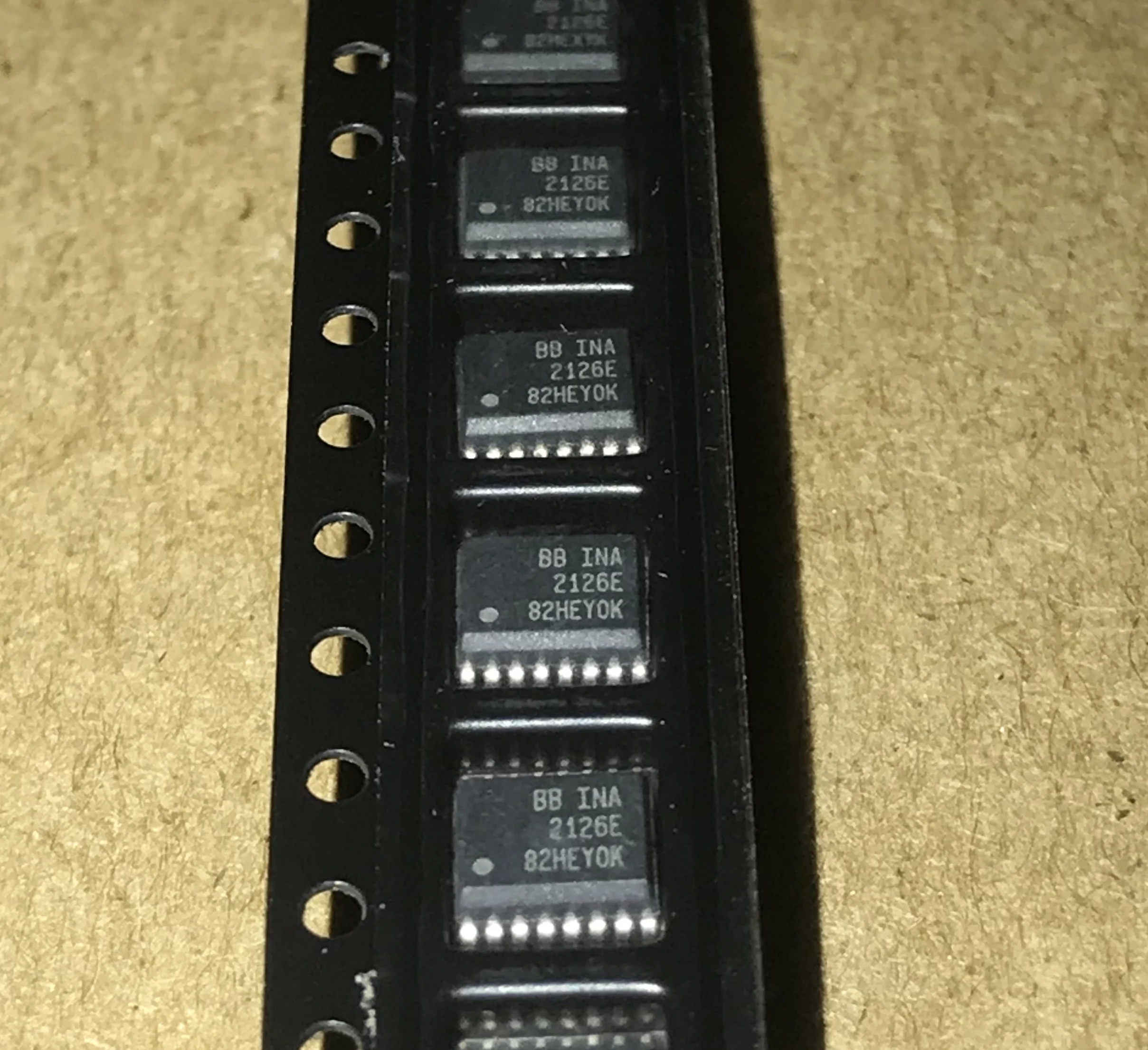
Introduction: This section highlights the important specifications and applications of the versatile INA2126P integrated circuit. With its wide range of features, this component offers exceptional functionality for various electronic designs.
Key Specifications: The INA2126P possesses a host of noteworthy specifications that contribute to its performance and versatility. These include high accuracy, low offset voltage, wide input voltage range, and a high common-mode rejection ratio. These specifications ensure reliable and precise signal amplification and measurement in a wide range of applications.
Applications: Thanks to its exceptional specifications and features, the INA2126P finds extensive use across diverse applications. It is commonly employed in precision instrumentation, industrial automation, medical equipment, and audio systems. Its ability to amplify small signals accurately and reject common-mode noise makes it suitable for demanding measurement and amplification tasks.
Signal Amplification: The INA2126P excels at amplifying small signals with high accuracy, making it ideal for applications that require precise measurements. It ensures minimal distortion, enabling the faithful reproduction of signals even at low amplitudes. Whether amplifying analog signals from sensors or transducers, or amplifying low-level audio signals, the INA2126P provides exceptional performance.
Noise Reduction: With its high common-mode rejection ratio, the INA2126P effectively suppresses common-mode noise, ensuring the reliability and accuracy of measured signals. This makes it suitable for applications that operate in noisy environments or involve high levels of interference. By eliminating unwanted noise, the INA2126P enhances signal integrity, leading to more accurate data acquisition and analysis.
Conclusion: The INA2126P stands out as a versatile integrated circuit with exceptional specifications and performance. Its wide range of applications, ranging from precision instrumentation to audio systems, attest to its reliability and versatility. Whether you require accurate signal amplification or noise reduction, the INA2126P offers an ideal solution for your electronic designs.
Understanding the Pin Configuration of Ina2126p
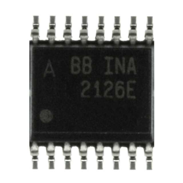
When working with the Ina2126p integrated circuit, it is important to have a clear understanding of its pin configuration. Each pin plays a crucial role in the overall functionality of the device, allowing for accurate measurement and control of current and voltage.
Starting with pin 1, this is typically the input pin through which the circuit receives the signal or current to be measured. It is essential to ensure proper connection and stability at this pin to obtain accurate readings. Moving on to pin 2, this serves as a reference pin, providing a stable voltage or current against which the measurements are taken.
Pin 3, also known as the output pin, carries the measurement results and provides the necessary output signal related to the input being measured. It is important to ensure sufficient load capacity for this pin to maintain signal integrity and prevent distortion.
Next, pin 4 is the power supply pin, which provides the necessary voltage or current to operate the device. It is crucial to correctly connect and regulate the power supply to ensure proper functioning of the Ina2126p. Finally, pin 5 is the ground pin, used to create a reference point for the entire circuit, ensuring stability and minimizing noise interference.
Understanding the pin configuration of the Ina2126p not only allows for proper connection and operation of the integrated circuit, but also ensures accurate measurement results and reliable performance. By following the guidelines and considerations for each pin, you can optimize the functionality and reliability of your circuit.
A Comprehensive Guide to Pin Functions and Their Significance
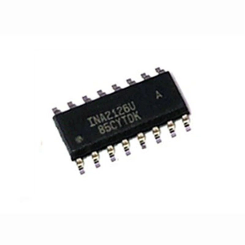
Understanding the roles and importance of pin functions is crucial for effectively utilizing electronic components in various applications. In this comprehensive guide, we will explore the diverse functions of pins in electronic devices and their significance in ensuring proper operation.
Different pins serve different purposes and play integral roles in the overall functionality of electronic components. Each pin has a specific function, such as providing power, transmitting signals, receiving data, or enabling control operations. Understanding these functions is essential for designing and troubleshooting circuits.
Power pins are responsible for supplying the necessary electrical power to the device. They may include VCC, VDD, or VSS pins and ensure stable voltage levels. The stability of the power supply directly influences the performance and reliability of the component.
Signal pins transmit data, information, or signals between various components or subsystems. These pins can be input or output pins, and their proper connection is vital for effective communication within the system. Ensuring correct signal routing is essential for accurate data transfer and overall system functionality.
Control pins are used to control the operation of the device. They allow for enabling or disabling specific functionalities, setting configuration parameters, or initiating specific actions. These pins often require specific voltages or trigger conditions to function correctly.
Ground pins act as a reference point for the electrical circuit and are essential for establishing a common ground potential. They provide a low impedance path for returning current from the device to the power supply, ensuring accurate voltage levels and minimizing noise interference.
Understanding the significance of pin functions helps in troubleshooting and optimizing circuit designs. By ensuring proper connection and utilization of each pin, engineers can maximize the performance, reliability, and efficiency of their electronic devices.
In summary, pin functions in electronic components are diverse and essential for proper device operation. Power pins maintain stable voltage supply, signal pins enable communication, control pins facilitate device operation, and ground pins establish a reference potential. Understanding the significance of each pin function is crucial for effective circuit design and troubleshooting.
Troubleshooting Common Issues with Ina2126p
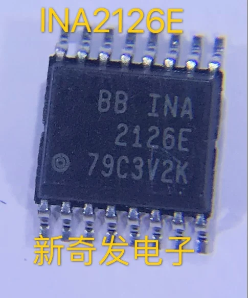
When working with the Ina2126p integrated circuit, it is important to be aware of potential issues that may arise during its operation. By understanding these common problems and their solutions, you can ensure optimal performance and address any challenges that may arise.
- Input Voltage Instability: One common issue that may occur with the Ina2126p is input voltage instability. This can lead to inaccurate readings and unreliable operation. To troubleshoot this problem, first, check the power supply connections and ensure they are secure. Additionally, inspect the input signal for any fluctuations or noise that may be causing the instability. Using filters or adjusting the amplification settings can help mitigate this issue.
- Output Signal Distortion: Another issue that may occur is output signal distortion. This can manifest as unwanted noise, harmonic distortion, or clipping. To troubleshoot this problem, start by examining the input signal and make sure it is within the specified range for the Ina2126p. Verify that the gain settings are appropriate for your application and adjust them if necessary. Additionally, check for any ground loop issues or electromagnetic interference that may be affecting the output signal quality.
- Temperature Drift: The Ina2126p may also experience temperature drift, where the device’s performance varies with temperature changes. To address this issue, ensure that the IC is operating within the specified temperature range. If the drift is significant, consider using thermal management techniques such as heat sinks or thermal pads to regulate the temperature and minimize its impact on the circuit’s accuracy.
- Incorrect Gain Calculation: Incorrect gain calculation can lead to inaccurate measurements and result in issues with the Ina2126p’s performance. To troubleshoot this issue, double-check the gain equation and ensure that all variables are correctly defined. Verify the resistor values and connections in the circuit to make sure they match the intended gain. Re-calculate the gain if necessary and verify the results using a known reference signal.
- Supply Voltage Limitations: The Ina2126p has specified supply voltage limitations that should be adhered to for proper operation. Exceeding these limits can result in malfunction or even damage to the IC. To troubleshoot this issue, check the supply voltage levels and ensure they are within the specified range. If the voltage is too high or too low, adjust the power supply or implement voltage regulators to maintain a stable and suitable voltage for the Ina2126p.
By understanding and addressing these common issues with the Ina2126p, you can optimize its performance and ensure reliable operation in your circuitry. It is important to carefully diagnose and troubleshoot any problems that arise, employing appropriate techniques and solutions to maintain accurate measurements and reliable signal processing.
A Handy Reference for Identifying and Resolving Problems in Circuit Design
In the world of circuit design, it is inevitable to encounter various challenges that can hinder the functionality and performance of electronic systems. This article serves as a valuable resource for engineers and designers, providing a comprehensive guide on identifying and resolving issues commonly encountered in circuit design. By understanding the underlying principles and employing effective problem-solving techniques, professionals can ensure optimal circuit performance and troubleshoot problems efficiently.
Understanding Common Issues
Before delving into specific problem-solving techniques, it is crucial to familiarize oneself with common issues that arise in circuit design. These issues can range from power supply-related problems to signal integrity issues, component failures, and electromagnetic interference. By knowing the typical symptoms and causes of these challenges, engineers can start troubleshooting effectively and identify the root cause of the problem.
Analyzing Circuit Performance
When faced with a circuit problem, it is essential to carefully analyze the performance of the circuit. This involves examining voltage and current levels, signal waveforms, and overall system behavior. By employing measurement tools and techniques, engineers can gather relevant data and assess the circuit’s performance against its intended specifications. This analysis serves as a basis for identifying deviations or abnormalities that may indicate a problem.
Identifying Root Causes
Once an issue is detected, the next step is identifying its root cause. By employing a systematic approach and utilizing troubleshooting expertise, engineers can narrow down the potential causes of the problem. This may involve inspecting and testing individual components, performing circuit simulations, or analyzing the circuit’s layout and connections. Through a logical and methodical process, engineers can pinpoint the exact source of the problem.
Implementing Solutions
After identifying the root cause, engineers can proceed to implement appropriate solutions. This may involve replacing faulty components, adjusting circuit parameters, modifying the circuit layout, or adding filtering techniques to mitigate noise and interference. It is crucial to document the implemented solutions and ensure they conform to the circuit’s design specifications. Thorough testing and validation should be performed to verify the effectiveness and stability of the implemented measures.
Continual Learning and Improvement
Circuit design is an ever-evolving field, and new challenges and techniques emerge constantly. Therefore, it is important for engineers and designers to engage in continual learning and improvement. Keeping up with industry advancements, attending technical workshops, and collaborating with peers can enhance problem-solving skills and expand the knowledge base. By continually improving their expertise, professionals can stay at the forefront of circuit design and effectively address any future issues that may arise.
In conclusion, this article provides a comprehensive reference for engineers and designers to identify and resolve problems in circuit design. By understanding common issues, analyzing circuit performance, identifying root causes, implementing solutions, and fostering continual learning, professionals can overcome challenges and ensure the successful operation of electronic systems.