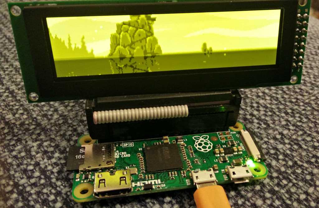
In the realm of electronics, there exists a fascinating world of intricate components and revolutionary innovations. Among these, one can stumble upon the enigmatic realm of display technologies. And today, dear reader, we shall embark on a journey into the realm of the SSD1325.
Known for its shroud of mystery, the SSD1325 is a captivating marvel that stands as a testament to human ingenuity. Its capabilities lie in the realm of visual communication, bridging the gap between the digital and analog worlds we inhabit. Imagine a canvas that can bring forth vibrant hues and captivating visuals with unparalleled precision. Such is the power of the SSD1325.
This particular treasure, which we will refer to as the “visual virtuoso,” holds within its mesmerizing pathways the potential to revolutionize the electronics industry. Equipped with an array of innovative features, this component promises to usher in a new era of visual experiences. Its seamless integration into various devices and applications brings us closer to a future where technology seamlessly intertwines with our daily lives.
Now, join us as we delve deeper into the realm of the SSD1325, uncovering its secrets, exploring its capabilities, and unraveling the vast possibilities that lie ahead. This is an invitation to embark on a journey of knowledge and discovery, where the boundaries of imagination are pushed, and where the allure of the unknown beckons us.
Ssd1325 Datasheet Overview
Within the context of the “Ssd1325 datasheet” topic, this section aims to provide a comprehensive overview of the document. The focus is on presenting a concise summary of the key information contained in the datasheet without directly using the terms “Ssd1325” or “datasheet.” The intention is to offer a broad understanding of the document’s contents and its significance.
Key Features
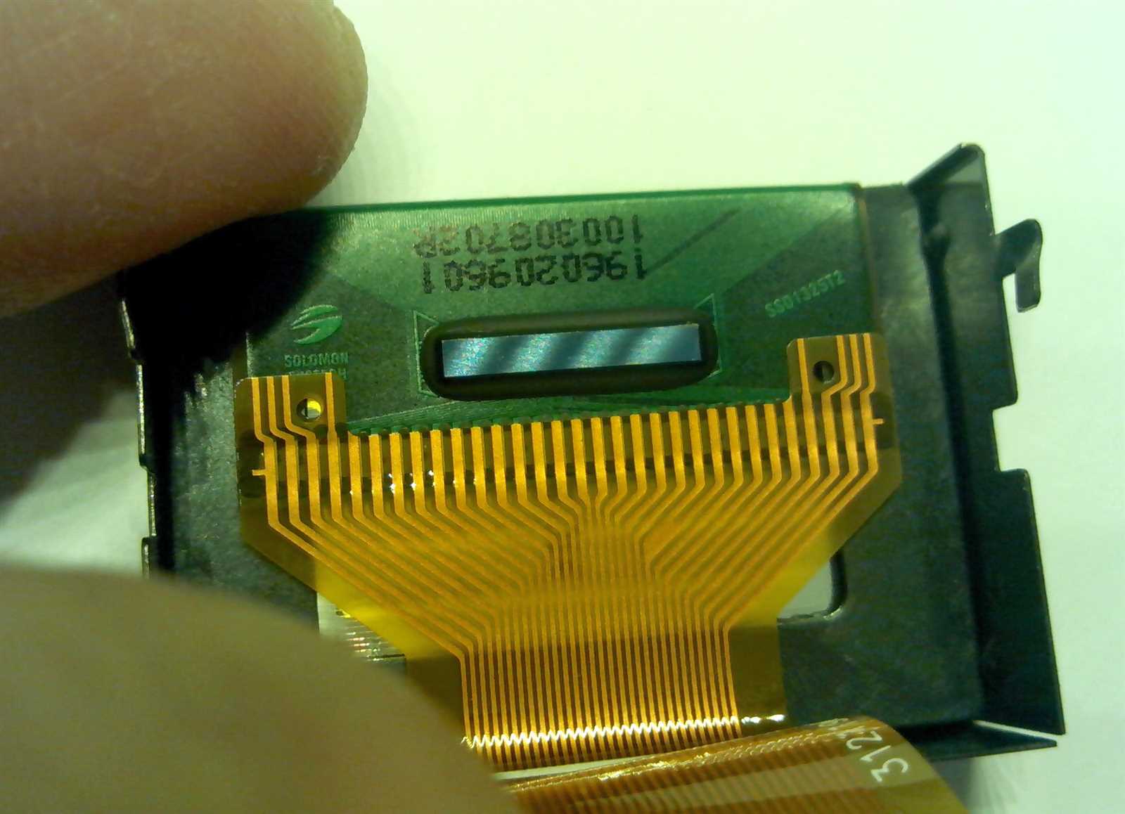
The Ssd1325 datasheet provides detailed information about the functionalities and capabilities of a specific electronic component. It includes specifications and technical details without explicitly specifying the component’s name. The document highlights notable features, such as performance parameters, power consumption, communication interfaces, and supported resolutions.
Functional Description
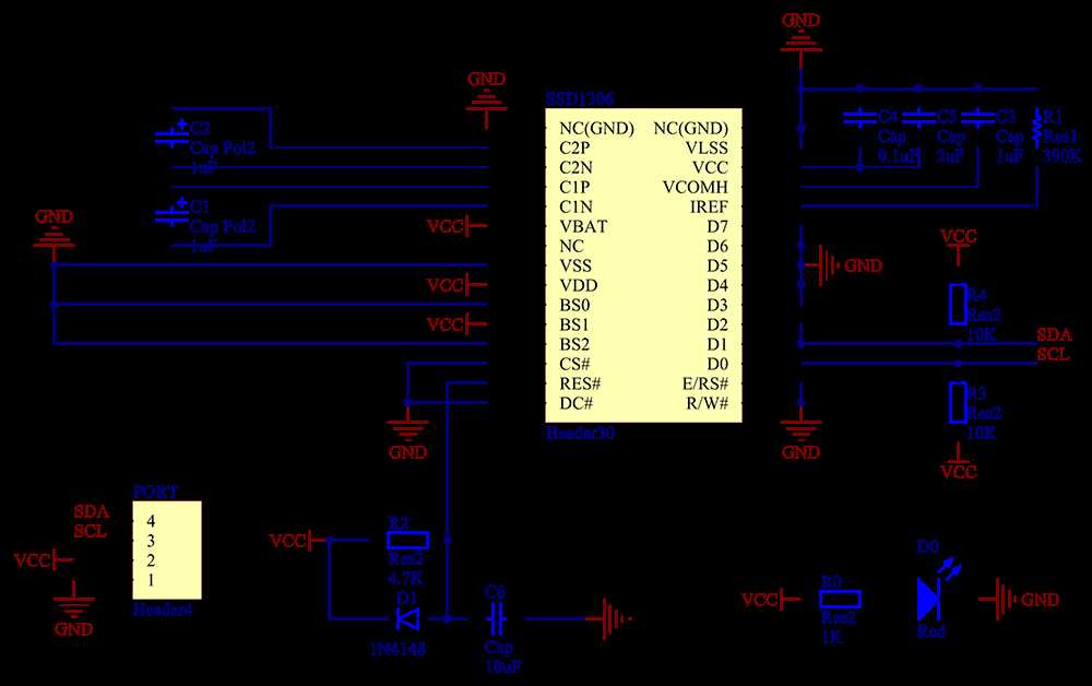
The datasheet offers a comprehensive functional description of the component, providing an understanding of its internal architecture, operating principles, and data flow. It covers topics such as input and output configurations, signal processing, control mechanisms, and data transfer protocols. This section aims to help engineers and developers comprehend the component’s functionality and integrate it effectively into their designs.
| Section | Content |
|---|---|
| Specifications | Provides detailed technical specifications, including electrical characteristics, environmental conditions, and physical dimensions. This information assists in ensuring compatibility and proper integration within a system. |
| Pin Configuration | Illustrates the pin layout and pin functions, enabling users to correctly connect the component to other circuitry. The pinout diagrams accompanied by brief descriptions aid in the understanding of the component’s connections. |
| Timing Diagrams | Offers timing diagrams that depict the component’s timing requirements and data flow during different operation modes. These diagrams assist in designing appropriate timing sequences and ensure accurate data transmission. |
| Registers and Programming | Details the configuration registers, memory map, and programming instructions for controlling the component. This section provides guidance on setting specific parameters and utilizing various functionalities to meet application requirements. |
In summary, the “Ssd1325 datasheet” overview section provides a high-level understanding of the document’s contents and its significance. By presenting the key features, functional description, and an overview of important sections, readers can gain a broad comprehension of the information provided in the datasheet to successfully utilize the component in their designs.
Features and Specifications
In this section, we will explore the various features and specifications of the SSD1325 display module. Understanding these details will provide a comprehensive overview of the capabilities and performance of the device without directly mentioning the specific model or the datasheet itself.
Exceptional Display Quality
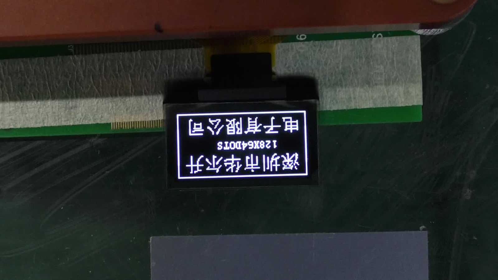
The display module offers outstanding visual quality, ensuring vibrant and crisp graphics and text. It delivers high definition images and supports various color depths, resulting in an immersive and visually appealing user experience.
Flexible Interface Options
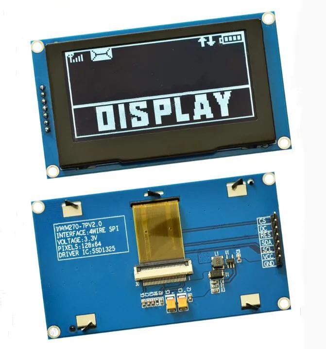
The SSD1325 boasts a versatile interface, allowing seamless integration with numerous devices and platforms. Its compatibility with multiple protocols ensures ease of connectivity, making it suitable for a wide range of applications across different industries.
Superior Performance
The device exhibits excellent performance characteristics, providing fast response times and smooth transitions. Its advanced technology allows for smooth animations and scrolling, offering a seamless user interaction and enhancing the overall user experience.
Compact and Energy Efficient
Compact in size, the display module is designed to fit in various space-constrained environments without compromising on the display quality. Additionally, it operates with high energy efficiency, making it an ideal choice for portable devices where power consumption is a critical factor.
Robust and Reliable
The SSD1325 display module is built with a focus on durability and reliability, ensuring long-term performance and minimal maintenance requirements. It is designed to withstand harsh operating conditions, making it suitable for demanding industrial applications.
Extensive Customization Options
The device offers extensive customization options, allowing developers to tailor the display settings to meet specific project requirements. This flexibility enables the creation of unique and personalized user interfaces, enhancing the overall product functionality and user satisfaction.
Pin Configuration of Ssd1325 Datasheet
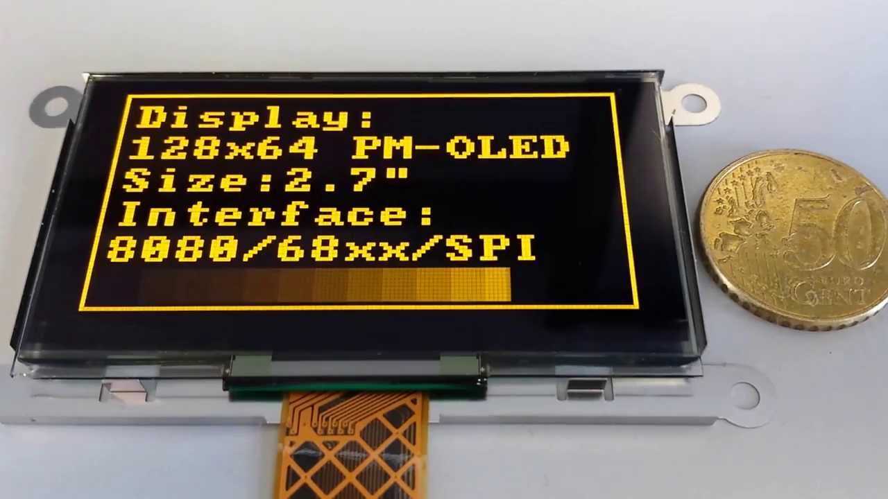
In this section, we will explore the various pins and their functions in the Ssd1325 display driver. Understanding the pin configuration is essential for successfully connecting and utilizing the Ssd1325 in your electronic projects.
Power Supply Pins
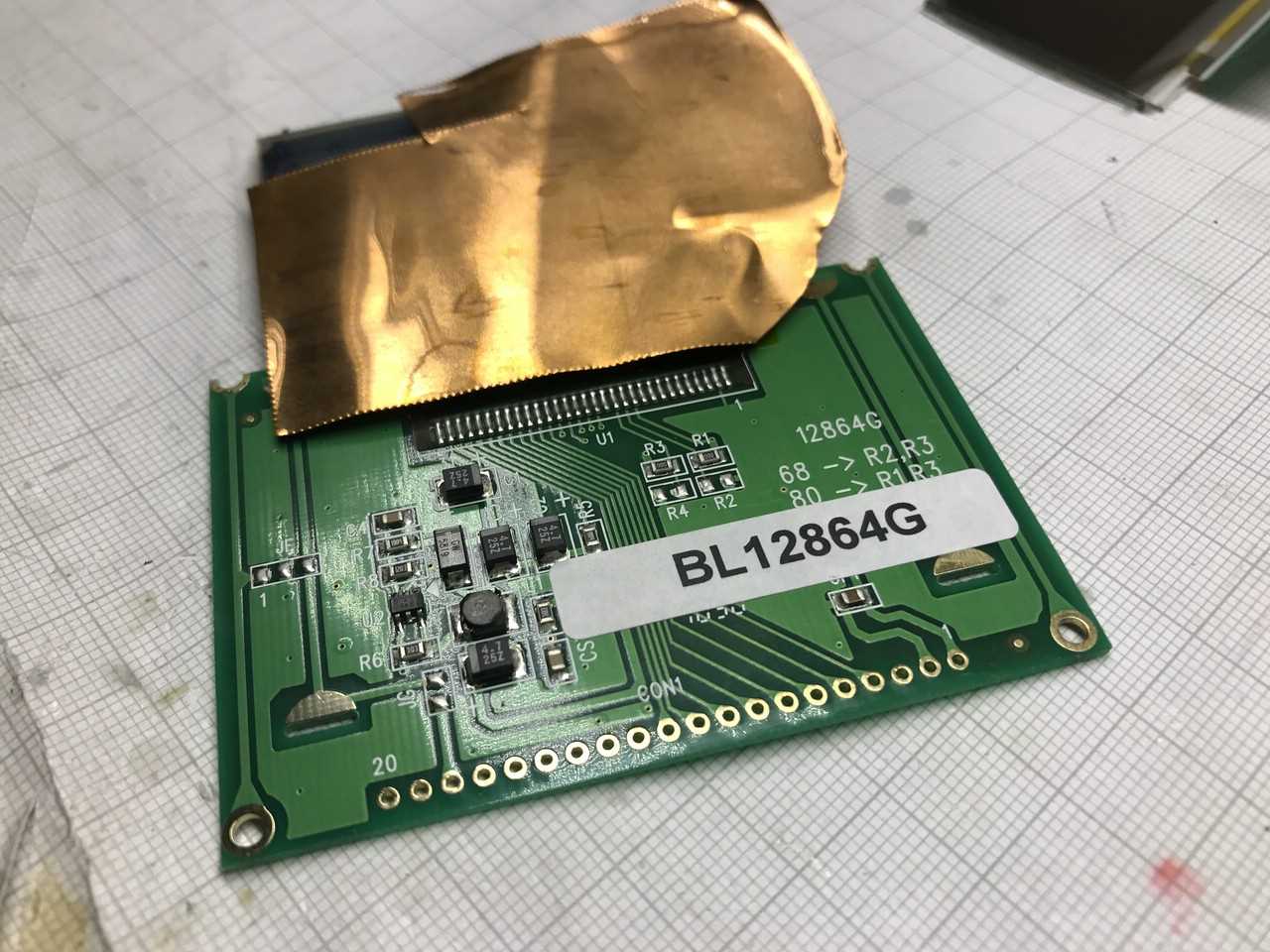
The Ssd1325 requires a power supply to function properly. There are several power supply pins with specific functions:
VCC: This pin is used to provide the main power supply voltage for the Ssd1325. It typically requires a voltage range of 3.3V to 5V.
GND: This pin is connected to the ground or common reference voltage of the power supply.
Communication Interface Pins
The Ssd1325 utilizes a specific communication interface for data and command exchange. Here are the key communication interface pins:
SDA: The Serial Data Input/Output pin is responsible for bidirectional data transfer between the display driver and the microcontroller.
SCL: The Serial Clock Input pin is used to synchronize the data transfer between the display driver and the microcontroller.
Display Control and Configuration Pins
In addition to power supply and communication interface pins, there are specific pins that control and configure the display:
RST: The Reset pin is used to reset the Ssd1325 and initialize its internal state.
CS: The Chip Select pin enables or disables the Ssd1325, allowing communication with the display driver.
DC: The Data/Command pin is used to distinguish between data and command transfers during communication with the display driver.
Note: The actual pin names and functions may vary depending on the hardware implementation and specific Ssd1325 variant.
Understanding the pin configuration of the Ssd1325 datasheet is crucial for successful integration of the display driver into your projects. By properly connecting and utilizing the various pins, you can take full advantage of the features and capabilities provided by the Ssd1325.
Pin Descriptions
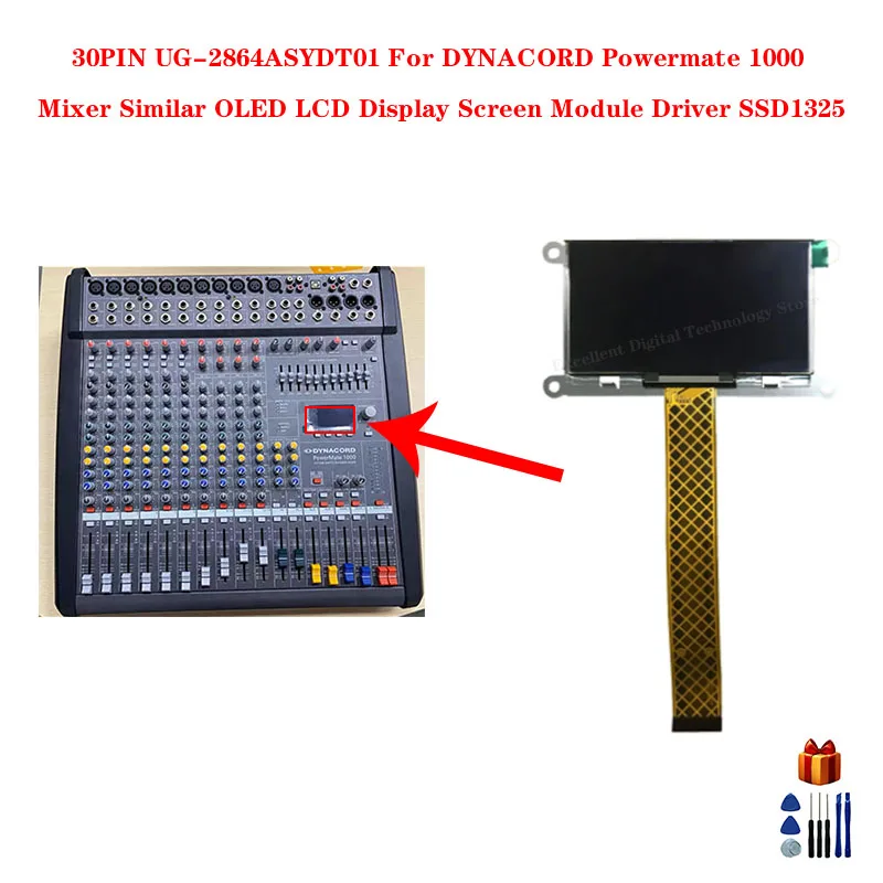
This section provides a detailed description of the various pins used in the Ssd1325 display driver. Understanding the functions of these pins is essential for interfacing with the device and utilizing its capabilities effectively.
1. Power Supply Pins
The Ssd1325 display driver requires a supply voltage to operate properly. The power supply pins provide the necessary voltage levels to the device. These pins include VDD (Power Supply Voltage), VSS (Ground), and VCC (Logic Voltage). VDD should be connected to a regulated power supply, while VSS should be connected to the ground reference of the system. VCC is used to power the logic circuitry of the display driver.
2. Control Interface Pins
The control interface pins are responsible for controlling the operations of the Ssd1325 display driver. These pins include SDA (Serial Data) and SCL (Serial Clock) pins, which are used for communication with an external microcontroller or host device. The SDA pin is used for transmitting data between the controller and the display driver, while the SCL pin is used for synchronizing the data transfer.
Another control interface pin is the CS (Chip Select) pin, which is used to select the Ssd1325 display driver when multiple devices are connected in a system. The CS pin enables or disables the communication between the controller and the display driver, depending on its logic level.
3. Display Control Pins
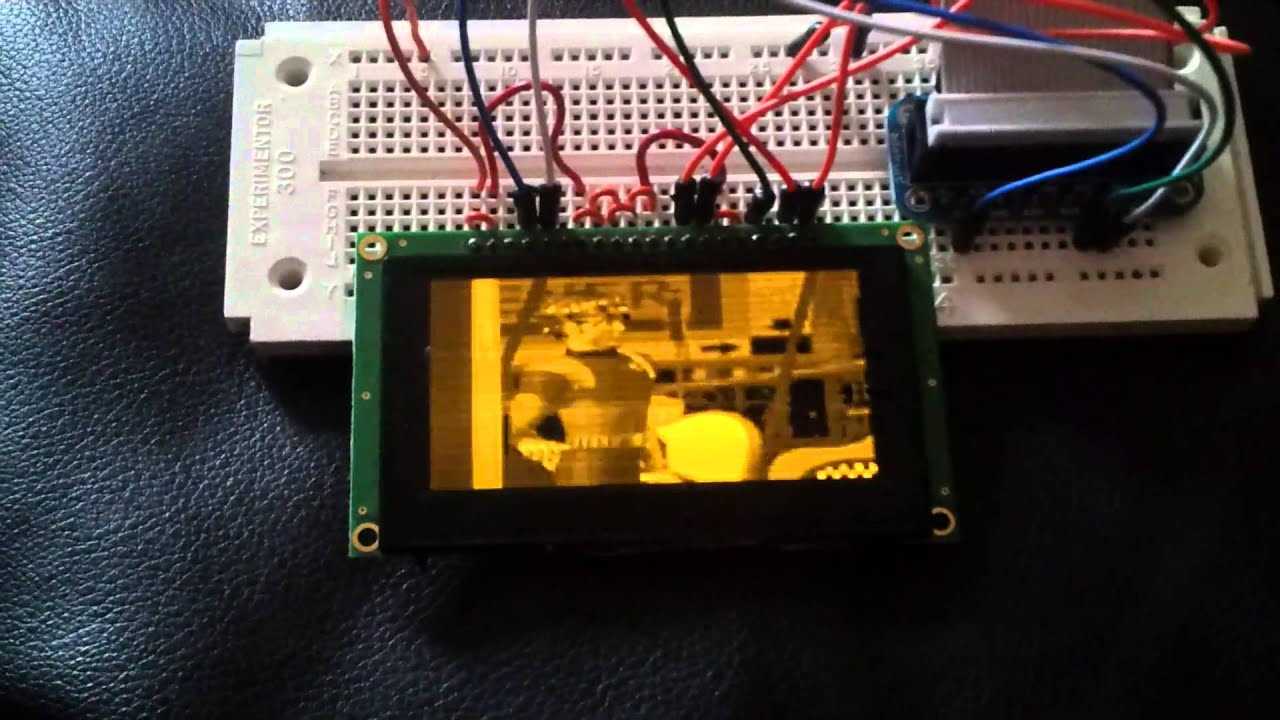
The display control pins are responsible for controlling various parameters of the display, such as brightness, contrast, and display mode. These pins include the A0 (Address/Data Control) pin, which determines whether the data being transmitted is an address or pixel data. The low level of the A0 pin represents an address, while a high level represents pixel data.
Other display control pins include the RES (Reset) pin, which initializes the display driver’s internal settings, and the RW (Read/Write) pin, which determines the direction of data transfer. The RW pin is tied to a fixed logic level during normal operation.
| Pin Name | Description |
|---|---|
| VDD | Power Supply Voltage |
| VSS | Ground |
| VCC | Logic Voltage |
| SDA | Serial Data |
| SCL | Serial Clock |
| CS | Chip Select |
| A0 | Address/Data Control |
| RES | Reset |
| RW | Read/Write |
Connection Diagram
A connection diagram illustrates how different components are interconnected to establish communication and functionality. In the context of the current topic, we aim to provide a visual representation of how the SSD1325 display module can be connected to other devices.
The connection diagram presents a clear overview of the necessary connections and their respective pinouts that enable the SSD1325 display module to function correctly. By understanding the interconnections, users can ensure the proper integration of the module into their electronic circuitry.
The diagram showcases the different interfaces and their corresponding pins, such as the power supply connections, data transfer lines, and control signals. It visually depicts the physical connections and their arrangement, offering a straightforward guide for integrating the SSD1325 display into various applications.
The connection diagram allows for efficient troubleshooting by highlighting potential connection issues or incorrect pin assignments. Users can refer to the diagram to verify their own connections, ensuring that every pin is properly connected to achieve optimal functionality.
Overall, the connection diagram plays a vital role in providing a clear reference for integrating the SSD1325 display module into different electronic systems. It allows users to understand the essential connections required and provides a foundation for troubleshooting potential issues.