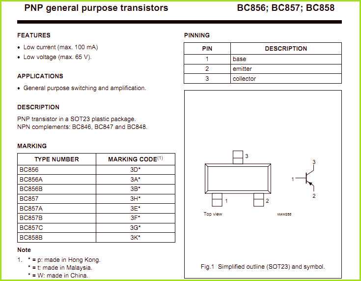
Imagine a world of sleek and compact electronic devices that fit snugly in the palm of your hand, each one harnessing the power of advanced technology to execute complex functions. At the heart of these marvels of modern engineering lies a crucial element known as the Surface Mount Device (SMD) transistor. This tiny but mighty component plays a pivotal role in delivering efficient and reliable performance, enabling devices to keep up with the fast-paced demands of our ever-evolving digital world.
Unbeknownst to many, the SMD transistor represents the epitome of miniaturization in the realm of electronic components. With its diminutive size, it defies the norms of traditional bulky transistors, opening up a whole new realm of possibilities for electronic devices. The SMD transistor’s compact design allows for it to be easily integrated into a wide range of applications, from smartphones and laptops to automotive systems and even medical devices, revolutionizing the way we interact with technology on a daily basis.
Don’t let its size fool you though – these mini powerhouses pack an incredible punch in terms of performance. The SMD transistor boasts unparalleled efficiency and speed, ensuring optimal power usage and seamless functionality. By providing low power consumption and high-speed switching capabilities, these components contribute significantly to enhancing device performance and extending battery life. Moreover, the SMD transistor’s ability to withstand high temperatures and operate in harsh environments makes it an ideal choice for industries where reliability is paramount.
In this comprehensive exploration, we delve into the intricacies of the SMD transistor, uncovering its inner workings and highlighting its essential characteristics. Join us as we embark on a journey to understand the fascinating world of SMD transistors, their diverse applications, and the vital role they play in shaping the future of cutting-edge technology.
Understanding SMD Transistor Datasheets
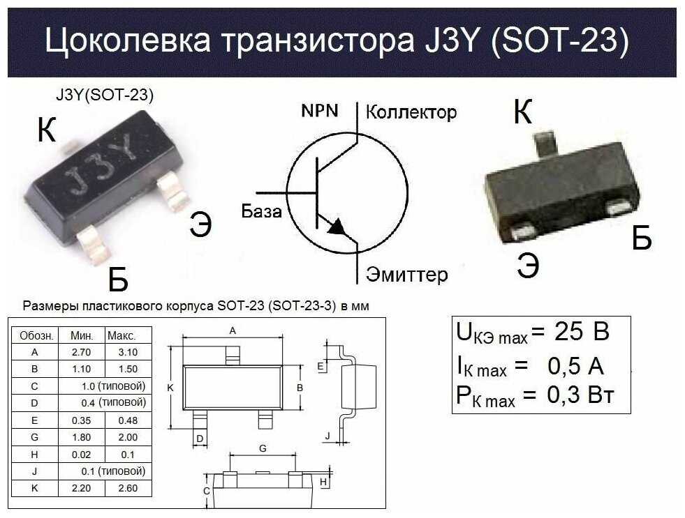
In the world of electronic components, SMD transistors play a crucial role. To fully comprehend the specifications and characteristics of these tiny devices, it is vital to acquire a clear understanding of the SMD transistor datasheets.
The datasheet of an SMD transistor serves as a comprehensive guide that provides crucial information about its performance, electrical characteristics, and usage guidelines. By studying these datasheets carefully, one can decipher the intricate details that are essential for successful integration and application of SMD transistors in electronic circuits.
- Component Identification: The datasheet generally includes a component identification section that contains details about the manufacturer, part number, and package type. This section allows engineers and designers to verify the authenticity and compatibility of the transistor with their specific application requirements.
- Electrical Ratings: Another crucial part of the datasheet is the electrical ratings section, which provides information about voltage, current, and power ratings. These ratings help determine the transistor’s capabilities in terms of its ability to handle electrical loads and its overall performance under various operating conditions.
- Characteristics and Specifications: Detailed specifications and characteristics are outlined in this section. It includes parameters such as gain, frequency response, switching speed, and noise figure, among others. Understanding these specifications is essential for making informed decisions when selecting the right SMD transistor for a particular application.
- Pin Configurations and Package Dimensions: The datasheet usually includes a section that provides the pin configuration and package dimensions of the SMD transistor. This information is crucial for proper installation and soldering onto the PCB (Printed Circuit Board) and ensures compatibility with existing circuit designs.
- Typical Application Circuits: This section of the datasheet showcases sample application circuits that can assist engineers in understanding how to incorporate the SMD transistor into their designs. It provides insights into the possible uses and provides a starting point for designing custom circuits.
By diving deep into the SMD transistor datasheets and analyzing the information provided, engineers can gain a comprehensive understanding of the performance, limitations, and potential applications of these essential electronic components. This knowledge is invaluable in designing and implementing successful electronic circuits that rely upon the efficient operation of SMD transistors.
Anatomy of an SMD Transistor Datasheet

When it comes to obtaining information about miniature electronic components, such as the small surface mount devices (SMD) transistors, one valuable resource is the datasheet. This comprehensive document serves as a vital reference point for engineers, designers, and hobbyists who seek detailed specifications and performance characteristics of SMD transistors.
Within the pages of a transistor datasheet, one can explore a wealth of information that unveils the inner workings and capabilities of these electronic components. It offers a curated collection of technical data, diagrams, and graphs that provide insights into the functionality, electrical characteristics, and usage guidelines.
By dissecting the anatomy of an SMD transistor datasheet, one can navigate through various sections that shed light on critical aspects of these components. Beginning with the general overview, the datasheet often includes a brief description of the device, its applications, and a summary of key features that distinguish it from other transistors.
One prominent section of the datasheet is dedicated to electrical characteristics. Here, readers can find details about parameters such as voltage ratings, current ratings, and power dissipation capabilities. This section may also present information on the transistor’s gain, frequency response, and noise figures, offering a comprehensive understanding of its electrical performance.
In addition to electrical characteristics, the datasheet often provides information about the physical dimensions and package outline of the SMD transistor. This allows engineers to assess how the component will fit into their circuit designs and offers insights into the device’s thermal properties, such as its junction-to-ambient thermal resistance.
Furthermore, the datasheet may include application-specific sections, illustrating the recommended operating conditions, appropriate soldering methods, and circuit layout considerations for optimal performance. This section also highlights potential limitations, such as maximum ratings and reliability data, ensuring that users understand the device’s boundaries and precautions to take during application.
Lastly, the datasheet typically contains ordering information, including part numbers, packaging options, and tape and reel specifications. Engineers and purchasers can utilize this information to identify the specific SMD transistor variant that best suits their needs and production requirements.
In conclusion, the anatomy of an SMD transistor datasheet brings together a range of vital information that enables engineers, designers, and hobbyists to evaluate, select, and integrate these miniature electronic components into their circuit designs. Through its carefully curated sections, the datasheet serves as a comprehensive guide, providing the necessary insights to harness the full potential of SMD transistors.
Key Parameters and Specifications
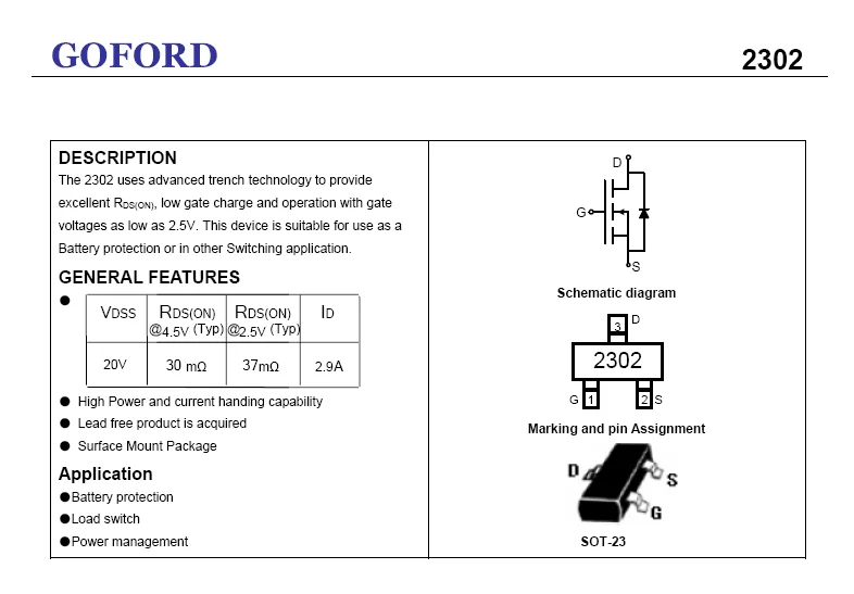
In this section, we will explore the important parameters and specifications that are crucial to understanding the characteristics and performance of SMD transistors. These parameters provide valuable insights into the functionality and capabilities of these electronic components, allowing engineers and technicians to make informed decisions when designing circuits and selecting the right transistor for their applications.
Electrical Characteristics:
One of the key aspects to consider when evaluating SMD transistors is their electrical characteristics. These characteristics include parameters such as voltage ratings, current ratings, and power dissipation. Voltage ratings signify the maximum and minimum voltages that the transistor can handle without causing damage. Current ratings indicate the maximum amount of current that can flow through the transistor. Power dissipation refers to the amount of power that the transistor can safely dissipate without overheating.
Gain:
The gain of a transistor is a measure of its ability to amplify signals. It is an essential parameter when designing amplification circuits. The gain is typically represented by the hFE or beta value, which is the ratio of the collector current to the base current. A high gain transistor amplifies signals more effectively, while a low gain transistor may not provide sufficient amplification.
Noise Figure:
Noise figure is a crucial parameter in applications where low noise performance is required, such as in RF circuits. It measures the amount of noise added by the transistor to the signal. A lower noise figure indicates better performance, as it signifies that the transistor adds less noise to the signal it amplifies.
Switching Speed:
Transistors are frequently used in applications that require fast switching speeds, such as digital circuits. The switching speed refers to how quickly a transistor can transition from an off-state to an on-state or vice versa. Faster switching speeds ensure efficient operation in high-frequency applications, where rapid switching is necessary.
Package Options:
SMD transistors are available in various package options, each with its own advantages and limitations. The package type influences factors such as size, heat dissipation, and ease of mounting. Common package types include SOT-23, SOT-223, and SOT-323. Selecting the appropriate package option is crucial to ensure compatibility with the overall circuit design and the specific requirements of the application.
Understanding and considering these key parameters and specifications enables engineers and technicians to make informed decisions when choosing SMD transistors for their electronic projects, ensuring optimal performance and reliability.
Interpreting and Applying the Datasheet Information
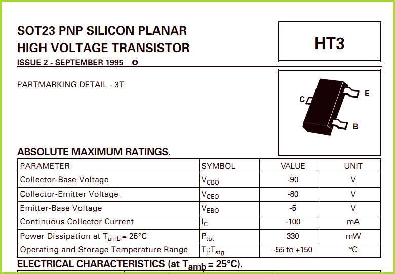
Understanding and effectively utilizing the information provided in a datasheet is crucial for successfully working with electronic components. The datasheet acts as a comprehensive guide, offering valuable insights into the characteristics, specifications, and performance of a particular component. In this section, we will explore the process of interpreting and applying the information presented in a datasheet, empowering you with the knowledge needed to make informed decisions and optimize component integration.
Unveiling Component Characteristics
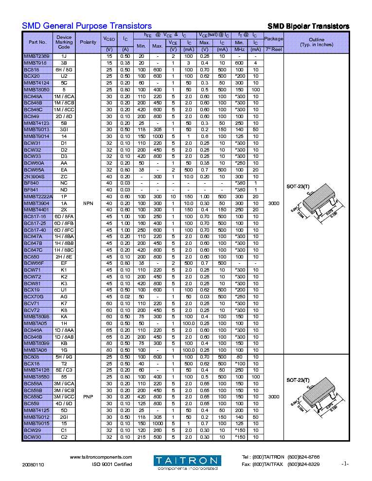
One of the primary purposes of a datasheet is to provide an in-depth analysis of the various characteristics of a component. These characteristics can include electrical, thermal, mechanical, and operational aspects. By carefully examining this section of the datasheet, you can gain a thorough understanding of the component’s behavior under different conditions, enabling you to determine its suitability for your specific application.
It is important to pay attention to key parameters such as voltage rating, current rating, power dissipation, and frequency response. These specifications allow you to assess the limits and performance boundaries of the component. Additionally, component-specific characteristics like gain, leakage current, input/output impedance, and noise figure provide insights into its functionality and potential impact on your overall circuit design.
Interpreting Performance Graphs and Curves
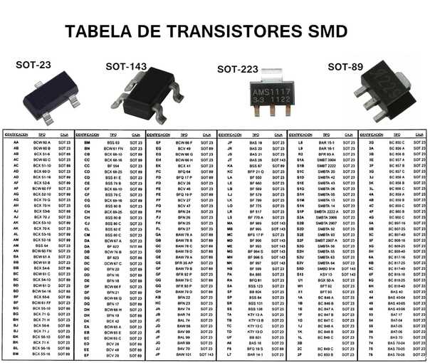
In addition to tabulated data, datasheets often present performance graphs and curves that depict a component’s behavior in a more visual and intuitive manner. These graphical representations can significantly aid in understanding complex relationships and making informed decisions concerning component selection and integration.
When interpreting performance graphs, look for trends, patterns, and critical points that denote optimum operating regions or limitations. Graphs can illustrate important aspects such as frequency response, temperature dependency, gain bandwidth product, and power dissipation shortfalls. By analyzing these visual representations, you can effectively evaluate a component’s performance in specific scenarios and determine its suitability for your project.
It is worth noting that performance graphs are often provided over a range of conditions, highlighting the component’s behavior under varying temperatures, voltages, and currents. Carefully considering these graphs allows you to pinpoint the component’s capabilities and limitations, facilitating optimal design choices.
Applying the Datasheet Information
Once you have interpreted the information provided in the datasheet, it is essential to apply this knowledge effectively to ensure successful integration of the component into your project. Consider the desired specifications and performance requirements of your application and cross-reference them with the values and limitations outlined in the datasheet.
Additionally, pay attention to any application-specific recommendations, guidelines, or precautions provided by the component manufacturer. These insights can be pivotal in optimizing the overall performance and reliability of your circuit. Furthermore, understanding the limitations and trade-offs associated with a component allows you to make informed design decisions, such as selecting appropriate bypass capacitors, adjusting biasing conditions, or implementing protective measures.
In conclusion, the datasheet serves as a valuable resource for engineers and electronics enthusiasts. By interpreting the characteristics, analyzing performance graphs, and effectively applying the information provided, you can ensure the successful integration of components and maximize the performance and reliability of your circuits.