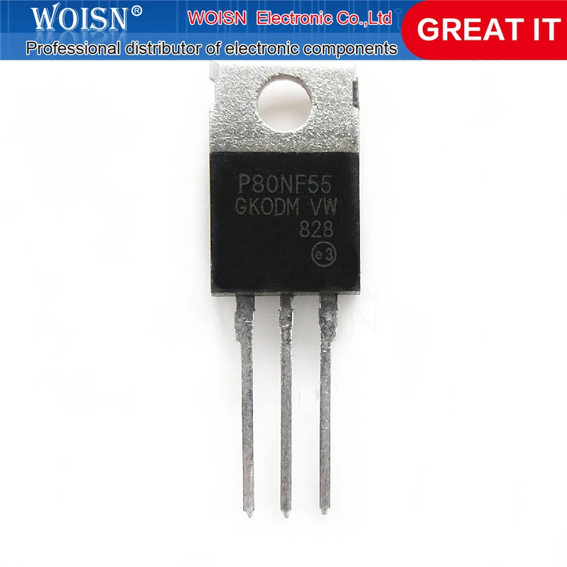
Delve into the intricate fabric of electronic engineering, where components reign supreme, each bearing a unique fingerprint in the symphony of circuitry. Within this realm lies a document shrouded in intrigue, harboring insights into the enigmatic entity that fuels the heart of innovation.
Embark on a journey through the labyrinthine corridors of technological prowess, where every curve and annotation holds the promise of revelation. This parchment, cloaked in the language of electrons and currents, serves as a map to decipher the secrets of a heralded component.
Unravel the tapestry of specifications and characteristics, each line a thread weaving the narrative of capability and potential. Here lies the lexicon of a silent titan, waiting to be deciphered by the adept and the curious alike.
Understanding the P80nf55 Documentation
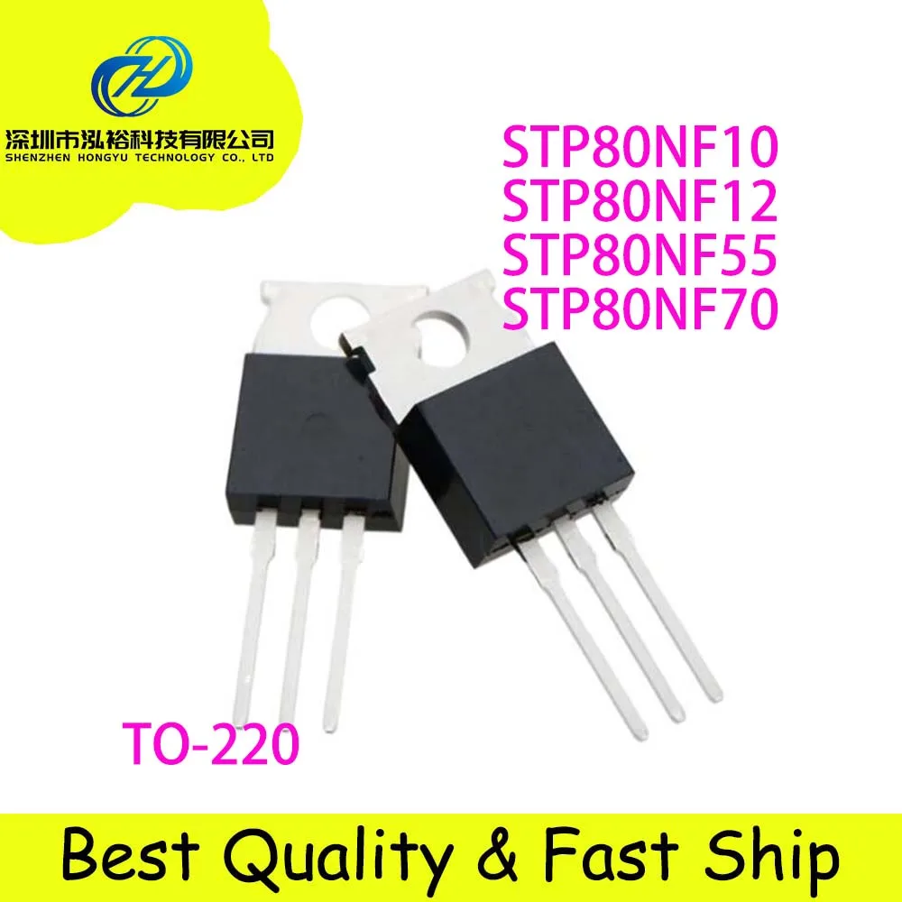
In delving into the intricacies of the technical documentation for the P80nf55 semiconductor component, one embarks on a journey to decipher the nuanced specifications and operational characteristics encapsulated within its datasheet. This section aims to elucidate the fundamental aspects of comprehending the essential information presented within.
Deciphering Technical Parameters
Upon perusing the documentation, one encounters a plethora of technical parameters and performance metrics delineating the functionality of the component. These metrics, ranging from electrical characteristics to thermal properties, serve as the bedrock for understanding the operational capabilities and limitations of the device.
Interpreting Graphical Representations
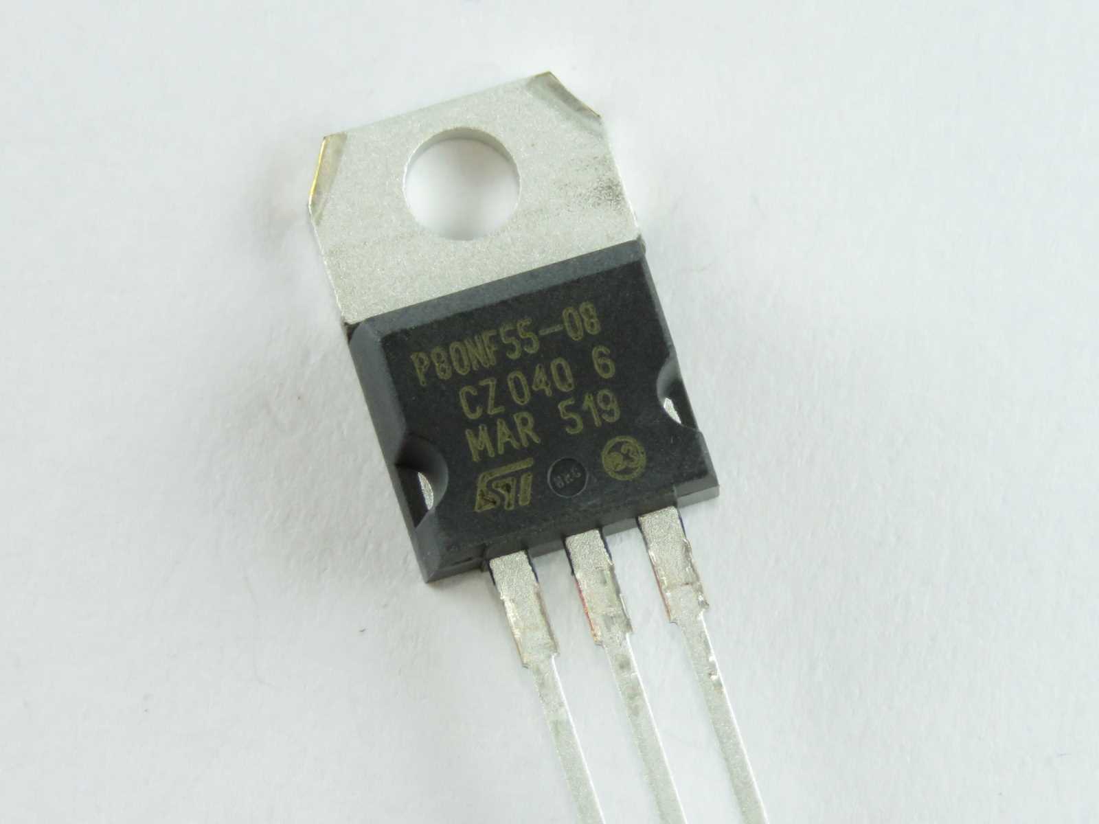
Beyond textual descriptions, graphical representations such as graphs and diagrams serve as invaluable aids in visualizing the behavior of the component under varying conditions. Understanding how to interpret these visual depictions enables engineers to glean insights into performance trends, aiding in optimal integration and utilization within electronic systems.
- Explore the intricacies of electrical characteristics
- Analyze thermal properties for effective heat management
- Decode application-specific information for tailored integration
Key Specifications and Performance Metrics
In this section, we delve into the essential specifications and performance indicators that characterize the capabilities and behavior of the component in question. We examine a spectrum of parameters and metrics that encapsulate its functionality, efficiency, and reliability, providing insights into its operational characteristics and potential applications.
Electrical Characteristics
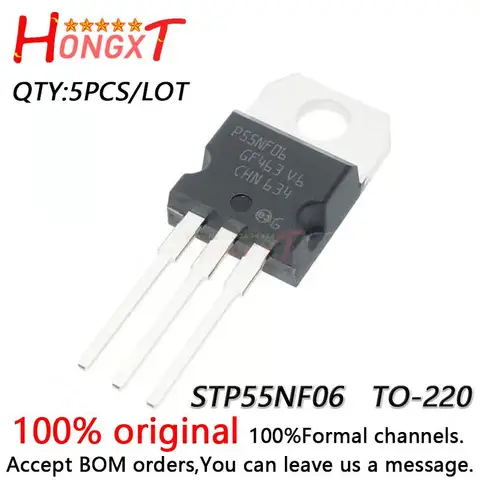
The electrical characteristics encompass a range of parameters detailing the component’s behavior under various operating conditions. These include voltage ratings, current handling capabilities, resistance, capacitance, and inductance. Understanding these metrics is crucial for designing circuits and systems that leverage the component effectively.
| Parameter | Description | Typical Value |
|---|---|---|
| Maximum Voltage Rating | The highest voltage the component can safely withstand. | XX volts |
| Continuous Current Rating | The maximum current the component can carry continuously without damage. | XX amps |
| On-Resistance | The resistance when the component is in the conducting state. | XX ohms |
| Capacitance | The ability to store charge, affecting switching speed. | XX picofarads |
| Inductance | The inherent property resisting changes in current. | XX microhenries |
Performance Metrics
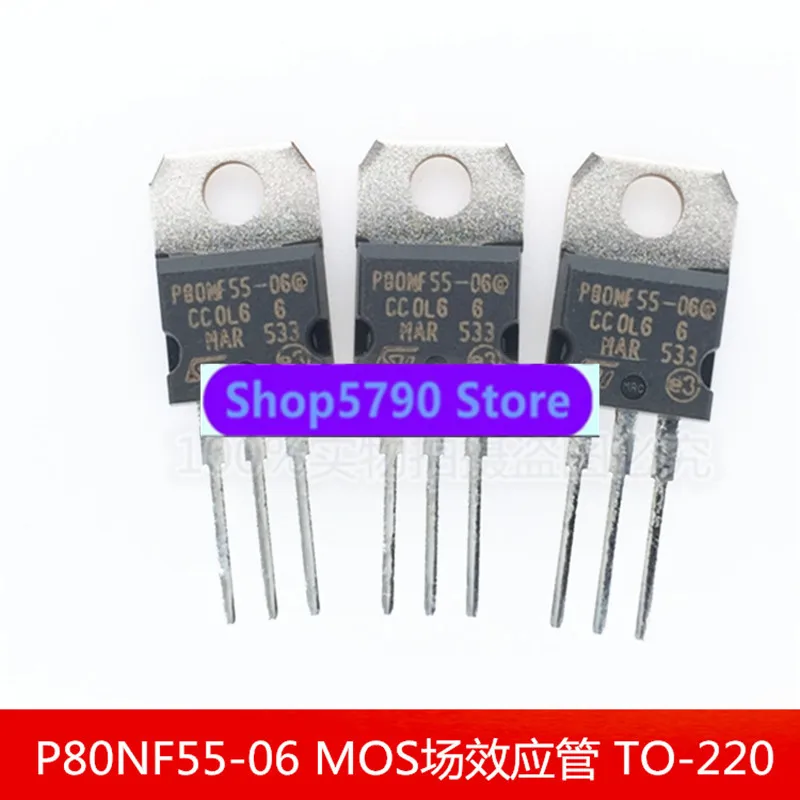
Performance metrics gauge the efficiency and effectiveness of the component in real-world scenarios. These metrics encompass parameters such as switching speed, thermal characteristics, and reliability measures, providing a comprehensive view of its operational prowess and suitability for diverse applications.
| Metric | Description | Typical Value |
|---|---|---|
| Switching Speed | The time taken for the component to transition between states. | XX nanoseconds |
| Thermal Resistance | The ability to dissipate heat generated during operation. | XX degrees Celsius per watt |
| Reliability Measures | Indicators of the component’s longevity and robustness under stress. | XX MTBF (Mean Time Between Failures) |
By examining these key specifications and performance metrics, engineers can make informed decisions regarding the integration of the component into their designs, ensuring optimal performance and reliability.
Application Circuit Design Guidelines

In this section, we provide comprehensive guidelines for designing effective application circuits to maximize the performance and efficiency of the device under consideration. Understanding the fundamental principles of circuit design is paramount in achieving optimal results. By following these guidelines, engineers can ensure the seamless integration of the component into their systems, enhancing functionality and reliability.
Component Selection
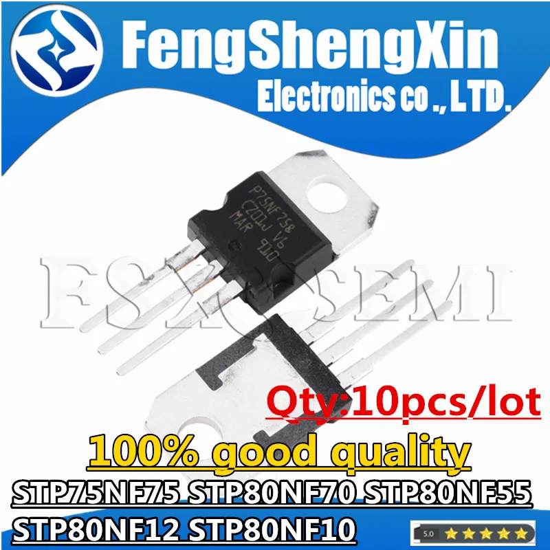
Choosing the appropriate components is the cornerstone of effective circuit design. It involves meticulous consideration of parameters such as voltage ratings, current handling capabilities, and thermal characteristics. Optimal component selection ensures compatibility and longevity, minimizing risks associated with overloading or underperformance.
Circuit Layout and Configuration
The layout and configuration of the circuit play a crucial role in its overall performance. Proper placement of components, attention to signal routing, and consideration of ground loops are vital aspects to be addressed. A well-designed layout reduces noise interference, enhances signal integrity, and facilitates efficient heat dissipation, contributing to the reliability and longevity of the circuit.
Interpreting Thermal Characteristics and Power Dissipation
In this section, we delve into comprehending the intricacies of thermal properties and the dissipation of power within electronic components. Understanding how heat affects performance and longevity is paramount in optimizing the functionality and reliability of electronic devices.
Thermal Characteristics
The thermal characteristics of a component refer to its ability to manage heat generation and dissipation. Analyzing these properties provides insights into how efficiently a device can operate under varying thermal conditions. Factors such as thermal resistance, junction-to-ambient thermal impedance, and thermal capacitance play pivotal roles in determining the thermal behavior of a component.
Power Dissipation
Power dissipation, often referred to as thermal dissipation, elucidates the process by which a component releases heat into its surroundings. It encompasses various mechanisms, including conduction, convection, and radiation. Accurate assessment of power dissipation aids in designing effective cooling systems to maintain optimal operating temperatures and prevent thermal-induced failures.
Interpreting Thermal Data
Interpreting thermal data entails deciphering information provided in datasheets or technical specifications regarding a component’s thermal performance. Key parameters such as thermal resistance, maximum junction temperature, and thermal impedance graphs offer invaluable insights into the thermal behavior of the component under different operating conditions. By leveraging this data, engineers can make informed decisions regarding component selection, thermal management strategies, and system-level optimizations.
Implications for Design and Reliability
The interpretation of thermal characteristics and power dissipation has profound implications for the design and reliability of electronic systems. Efficient thermal management not only enhances device performance but also extends its operational lifespan. By employing appropriate thermal design techniques, such as heat sinks, thermal vias, and proper layout considerations, designers can mitigate thermal challenges and ensure the longevity and reliability of electronic devices.