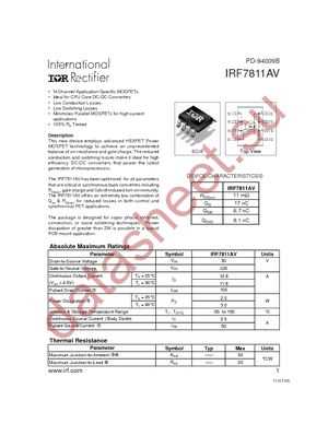
In the world of electronics, there exists a small yet powerful component that bridges the gap between two disparate systems. Its function is akin to that of a linguistic translator, ensuring smooth communication between different elements, while maintaining their individual integrity. This enigmatic device is known as the Moc 7811 micro optocoupler.
The Moc 7811 is a compact electronic coupling device that offers a seamless interface between low voltage input and high voltage output circuits. Its remarkable ability to transmit signals across isolated electric domains is a testament to the genius of modern engineering. With its intricate construction and innovative design, this micro optocoupler serves as a reliable conduit for data transmission, making it an indispensable component in a wide range of electronic applications.
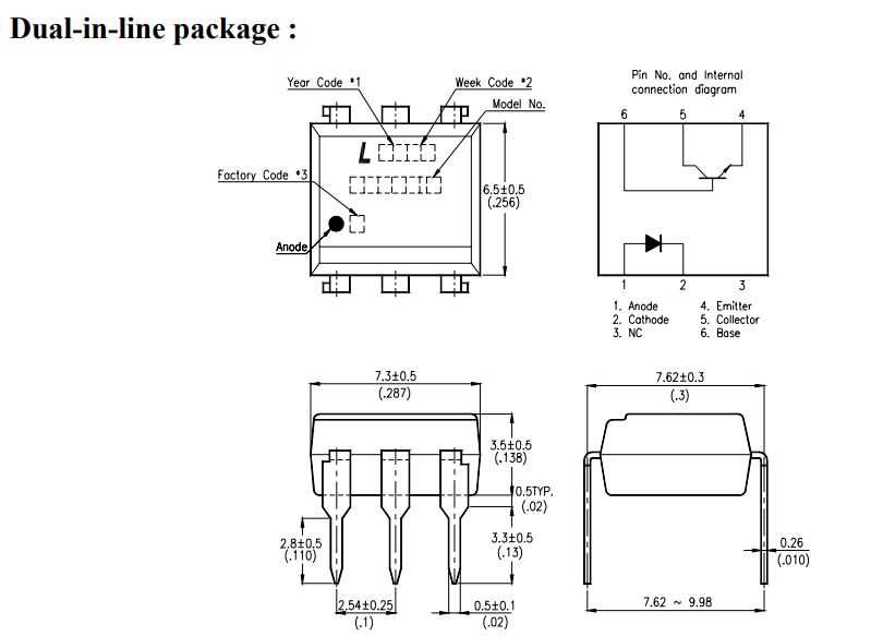
Equipped with an LED emitter and a phototransistor receiver, the Moc 7811 establishes a secure connection between two electrically isolated systems. The LED emitter converts electrical signals into optical pulses, which are then received by the phototransistor. This conversion from electrical to optical and back again ensures complete electrical isolation, protecting sensitive components from voltage surges, noise interference, and ground loops.
The versatility of the Moc 7811 is truly remarkable. Whether it is used to control motors, relay switches, or communicate with I/O boards, this micro optocoupler plays a crucial role in maintaining the stability and reliability of electronic systems. Its compact size, low power consumption, and high-performance characteristics make it an ideal choice for engineers and enthusiasts alike.
Understanding the Key Features and Applications
In this section, we will explore the various characteristics and potential uses of the Moc 7811 component. By gaining a comprehensive understanding of its key features, you will be able to leverage its capabilities efficiently in various electronic systems and applications.
Reliability and Durability
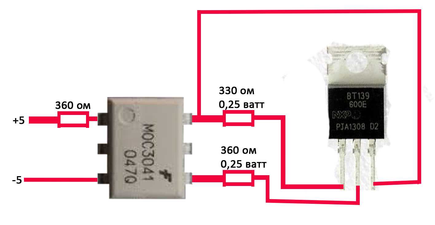
The Moc 7811 is known for its exceptional reliability and durability, making it an ideal choice for demanding electronic applications. Its robust construction ensures long-term performance and resistance to various environmental factors, including temperature variations and mechanical stress. This reliability makes it suitable for use in critical systems where accuracy and dependability are essential.
Sensor Functionality and Precision
The Moc 7811 acts as an optical sensor, accurately detecting changes in light intensity and converting them into electrical signals. This component’s high precision allows it to provide precise and consistent measurements, making it invaluable in applications that require accurate detection and monitoring. From detecting object proximity in automation systems to measuring light levels in ambient light sensing applications, the Moc 7811 offers versatile functionality.
Signal Amplification and Noise Reduction
One of the notable features of the Moc 7811 is its ability to amplify weak signals and filter out unwanted noise. This capability ensures the accuracy of the detected signals and minimizes the influence of external disturbances, resulting in reliable and consistent data. It is particularly useful in low-level signal applications where maintaining signal integrity is crucial.
Applications
The Moc 7811 finds application in a wide range of industries and systems. It is commonly used in home automation, robotics, industrial control systems, and security systems for its reliable sensing capabilities. Additionally, it can be integrated into consumer electronics, such as digital cameras or smartphones, for various sensing and detection functions. Its versatility and robustness make it a go-to choice for engineers and designers across different fields.
Technical Specifications and Pin Configuration of Moc 7811

In this section, we discuss the various technical specifications and pin configuration of the Moc 7811 sensor module, a well-known electronic component used in optocouplers for various applications. We will delve into the features and characteristics that make the Moc 7811 an essential component for designers and engineers.
The Moc 7811 boasts a range of impressive technical specifications, ensuring reliable and accurate performance. It offers high sensitivity and low power consumption, making it ideal for use in low-light environments. With its excellent noise immunity and high isolation voltage, the Moc 7811 provides stable and secure signal transmission.
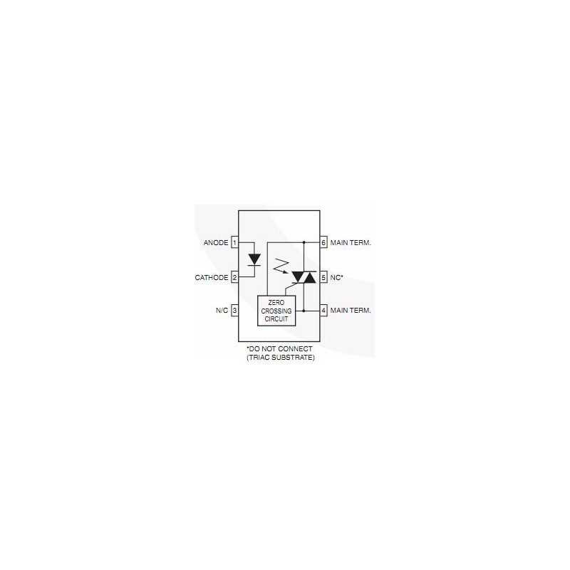
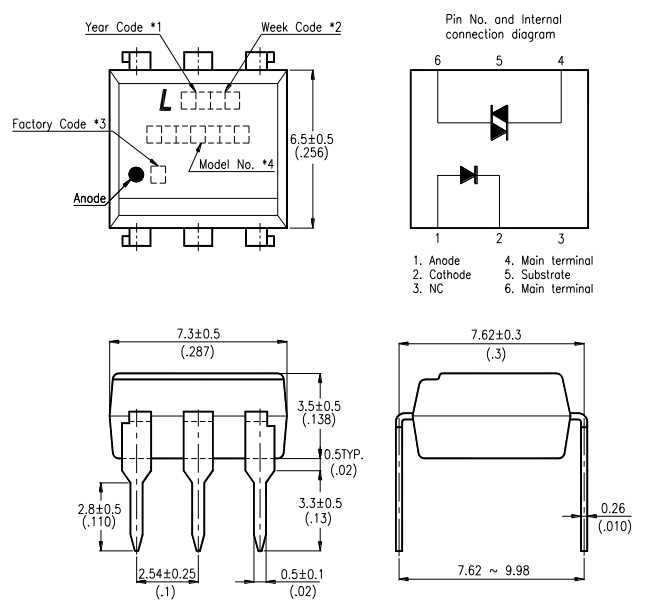
Furthermore, the pin configuration of the Moc 7811 module contributes to its versatility and ease of use. It consists of multiple pins with specific functions, enabling seamless integration into various circuit designs. These pins include an anode, cathode, and control elements, each serving a crucial role in the optocoupler circuit.
| Pin Name | Description |
|---|---|
| Anode (A) | A terminal connected to the anode of the internal LED, providing the positive polarity of the supply voltage. |
| Cathode (K) | A terminal linked to the cathode of the internal LED and acting as the reference point for the ground connection. |
| Control (C) | A terminal that controls the switching operation by applying an external voltage to activate the internal phototransistor. |
By understanding the technical specifications and pin configuration of the Moc 7811, engineers can harness its capabilities to design innovative and reliable electronic circuits. Whether it’s for industrial automation, medical devices, or communication systems, the Moc 7811 proves to be a valuable component in various applications.
Exploring the Electrical Characteristics and Pinout Diagram
In this section, we will delve into the intricate details of the electrical characteristics and pinout diagram of the Moc 7811 device. Understanding these key aspects is essential for a comprehensive understanding of the device’s functionality and its potential applications.
Electrical Characteristics
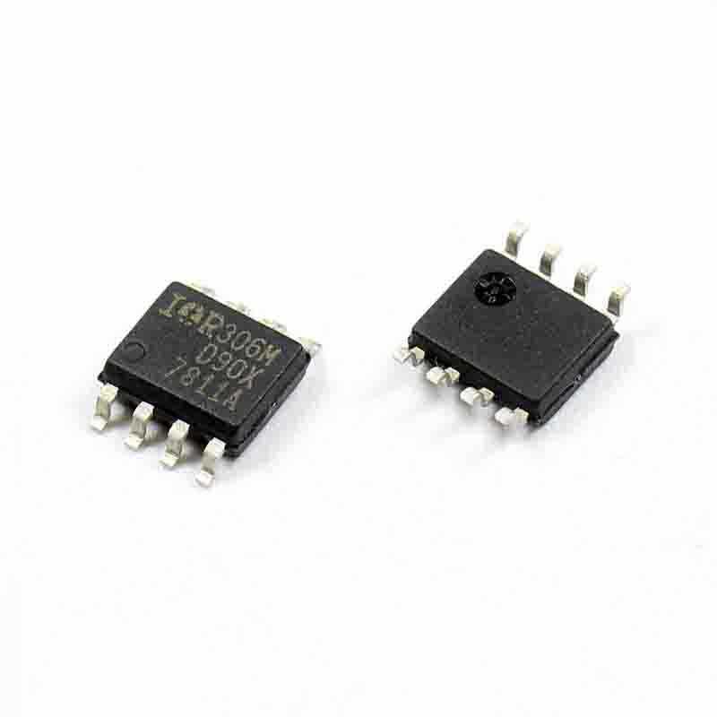
The electrical characteristics of the Moc 7811 device provide essential information about its performance and behavior in different operating conditions. These characteristics include parameters such as supply voltage, input current, and output voltage. By studying these characteristics, engineers can determine the compatibility of the device with their specific circuit design requirements.
Furthermore, the electrical characteristics also encompass details about the device’s power consumption, input and output impedance, and frequency response. These parameters play a crucial role in assessing the device’s suitability for various applications, including signal amplification, power control, and digital signal processing.
Pinout Diagram
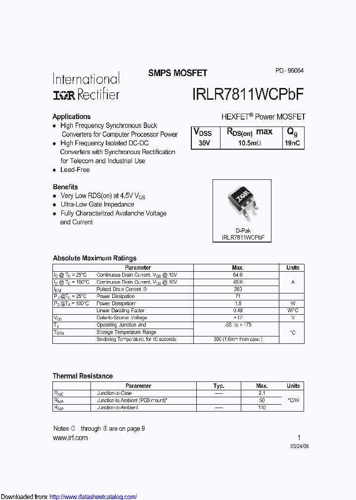
The pinout diagram of the Moc 7811 device serves as a visual representation of its internal structure and connectivity. It provides a layout of the device’s pins and their corresponding functions, enabling engineers to establish the necessary connections with other components in their circuit design.
The pinout diagram typically includes pins for supply voltage, ground, input signal, and output signal. Additionally, it may incorporate pins for auxiliary functions such as feedback control, temperature monitoring, or voltage adjustment. By referring to the pinout diagram, engineers can ensure proper integration of the Moc 7811 device within their circuit design.
To summarize, exploring the electrical characteristics and pinout diagram of the Moc 7811 device offers valuable insight into its operational capabilities and connectivity options. This understanding forms the foundation for leveraging the device’s potential in various electrical and electronic applications.
| Electrical Characteristics | Pinout Diagram |
|---|---|
| Provides information about device performance under different operating conditions | Visual representation of internal structure and connectivity |
| Determines compatibility with circuit design requirements | Identifies necessary connections with other components |
| Includes details about power consumption, impedance, and frequency response | Illustrates pins for supply voltage, input/output signals, and auxiliary functions |
Considerations for Choosing and Implementing Moc 7811
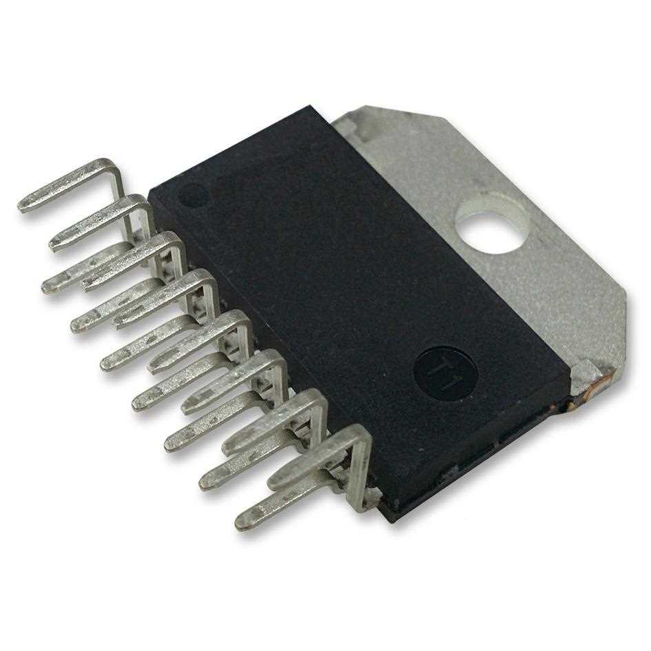
When selecting and incorporating the Moc 7811 into your project, it is important to consider several key factors that will ensure its successful implementation. Taking into account various considerations will enable you to make an informed decision and effectively utilize the capabilities of the Moc 7811.
Compatibility with Application Requirements
Firstly, it is crucial to evaluate the compatibility of the Moc 7811 with the specific requirements of your application. Consider the range of voltages, currents, and frequencies that you anticipate to encounter in your project. Assessing the Moc 7811’s ability to operate in these desired ranges will guarantee optimal performance and prevent any potential issues that may arise from incompatibilities.
Reliability and Durability
Additionally, the reliability and durability of the Moc 7811 play a significant role in its selection and implementation. Consider the quality and reputation of the manufacturer, as well as any certifications or standards compliance that the component may possess. Robustness and resistance to external factors such as temperature variations, vibrations, or electromagnetic interference are also important aspects to consider.
Moreover, examine the expected lifespan and stability of the Moc 7811 to ensure that it meets the long-term requirements of your application. This is particularly crucial in applications where frequent replacements or repairs are impractical or come with significant costs.
Lastly, take into account the power consumption and energy efficiency of the Moc 7811. Assess whether it aligns with the energy-saving goals of your project and whether it operates with minimal power wastage, allowing for sustainable and environmentally-friendly implementations.
By carefully considering the aforementioned factors, you can confidently select and successfully integrate the Moc 7811 into your project, harnessing its capabilities for seamless and efficient operation.
Tips for Optimal Performance and Integration in Electronic Circuits
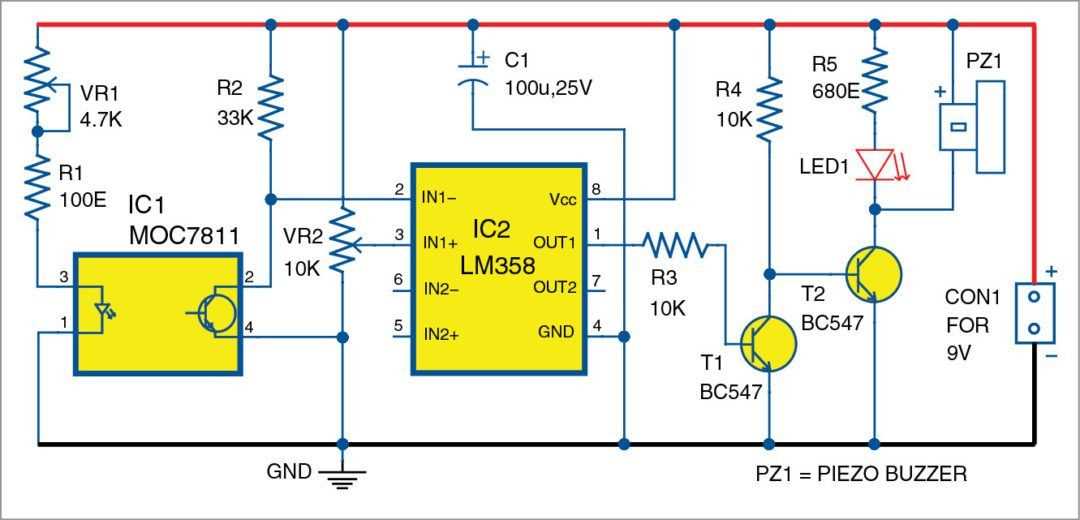
In order to ensure the smooth functioning and seamless integration of electronic circuits, it is crucial to follow certain guidelines for optimal performance. This section provides useful tips and strategies to enhance the efficiency and effectiveness of electronic circuits, optimizing their overall performance.
1. Component Selection: Carefully select components that are suitable for the specific requirements of your circuit. Consider factors such as voltage ratings, current ratings, and package sizes to ensure compatibility and reliability.
2. PCB Layout: Pay attention to the layout of the printed circuit board (PCB) as it greatly affects the performance of the circuit. Optimize the placement and routing of components to minimize signal interference, reduce noise, and enhance signal integrity.
3. Grounding and Shielding: Implement proper grounding techniques and use shielded cables to minimize electromagnetic interference and ensure accurate signal transmission. Separate analog and digital grounds to avoid cross talk and signal degradation.
4. Power Supply: Provide a stable and reliable power supply to the circuit by using appropriate voltage regulators and decoupling capacitors. This helps to eliminate voltage fluctuations and improve the overall performance and longevity of the circuit.
5. Thermal Management: Take into consideration the heat dissipation requirements of your circuit. Use heat sinks, thermal pads, and adequate ventilation to prevent overheating, which can lead to component failure and reduced performance.
6. Testing and Prototyping: Thoroughly test and prototype your circuit to identify and address any potential issues or flaws. Use simulation software and advanced testing equipment to validate the design, optimize performance, and ensure reliability.
7. EMI/EMC Compliance: Follow electromagnetic interference (EMI) and electromagnetic compatibility (EMC) standards to mitigate interference and maintain the stability of the circuit. Implement necessary shielding and filtering techniques to minimize EMI and EMC issues.
By implementing these tips and strategies, you can enhance the performance, reliability, and integration of electronic circuits, ensuring their seamless operation and functionality.