Exploring the intricacies of the latest electronic components entails delving into comprehensive documents that serve as blueprints for engineers and enthusiasts alike. Within these documents lie a treasure trove of vital information, guiding the design and implementation of innovative circuits and systems.
Unveiling the essence of these documents demands a nuanced understanding of the language employed, transcending mere technical jargon to convey the essence of functionality and performance. Each specification offers a glimpse into the capabilities and limitations of the components, paving the way for informed decision-making in the realm of electronics design.
Embarking on a journey through these datasheets, enthusiasts and professionals alike navigate through a labyrinth of parameters, uncovering the potential applications and optimal operating conditions for each component. It’s a meticulous process that requires attention to detail and a discerning eye for interpreting the nuances within the technical descriptions.
Peering into the heart of these documents, one can discern patterns of innovation and evolution, tracing the lineage of electronic components from their inception to their current state. Amidst the sea of specifications lies the MC14001BCP, a beacon of technological prowess, awaiting exploration and exploitation in the realm of electronic design.
Understanding MC14001BCP Datasheet: Key Features and Specifications
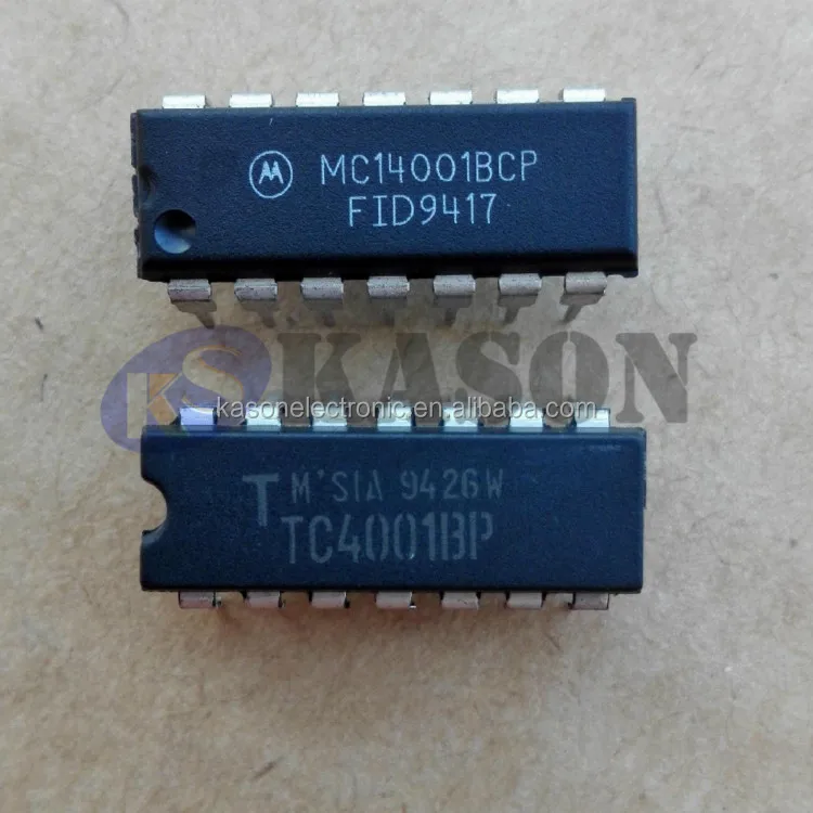
In exploring the intricacies of this electronic component, we delve into its defining characteristics and performance metrics, unraveling the essential details encapsulated within its documentation. Let’s embark on a journey to comprehend the core functionalities and technical specifications that shape its functionality.
- Operating Parameters: Delve into the operational boundaries, encompassing voltage ratings, temperature ranges, and frequency thresholds.
- Functional Overview: Uncover the primary tasks and operations it executes, elucidating its role within electronic systems.
- Interface Compatibility: Explore its compatibility with various input and output interfaces, elucidating connectivity options.
- Performance Metrics: Analyze metrics such as speed, power consumption, and signal-to-noise ratios, gauging its efficiency and effectiveness.
- Integrated Features: Examine built-in functionalities like logic gates, flip-flops, or other integrated circuits, elucidating their contributions to overall performance.
- Application Insights: Gain insights into potential applications across diverse domains, from consumer electronics to industrial automation.
- Package Details: Investigate the physical packaging, dimensions, and pin configurations, crucial for integration into electronic layouts.
- Reliability and Durability: Assess factors influencing long-term performance and robustness, ensuring stable operation over extended periods.
By comprehensively understanding the intricacies of the MC14001BCP, we equip ourselves with the knowledge necessary to leverage its capabilities effectively in diverse electronic designs.
Exploring the Functional Diagram and Pin Configuration
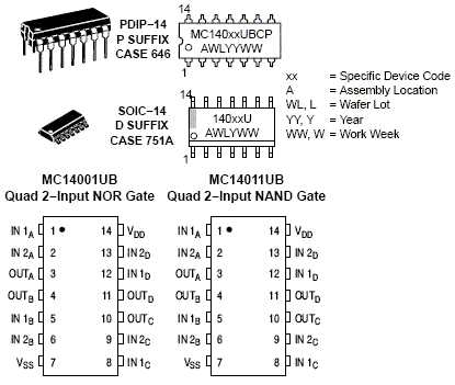
In this section, we delve into the intricacies of the functional diagram and pin configuration of the electronic component under scrutiny. By unraveling the functional diagram, we uncover the underlying architecture and operational principles, shedding light on its inner workings. Concurrently, a detailed examination of the pin configuration elucidates the connectivity and interface aspects essential for its integration within electronic circuits.
Functional Diagram Overview
The functional diagram serves as a visual representation of the component’s operational framework, showcasing the interrelation of its various internal components and subsystems. Through this diagram, we gain insights into the signal flow, logic pathways, and functional blocks constituting the component’s design. It provides a blueprint for understanding how input signals are processed, modified, and propagated to produce desired output responses.
Pin Configuration Analysis
The pin configuration of the component delineates the external interface points through which it interacts with external circuitry. Each pin serves a specific purpose, ranging from power supply input, signal input/output, to control and configuration interfaces. By scrutinizing the pinout arrangement and associated functionalities, we discern the roles and responsibilities of each pin in facilitating seamless integration within electronic systems. Understanding the pin configuration is paramount for correct placement and connection within circuit layouts, ensuring optimal performance and functionality.
- Gain insights into the operational framework through the functional diagram.
- Discern the roles and responsibilities of each pin in the pin configuration.
- Understand signal flow, logic pathways, and functional blocks within the component.
- Facilitate seamless integration within electronic systems by grasping the pinout arrangement.
Maximizing Performance: Application Insights and Best Practices
Unlocking the full potential of electronic components requires a comprehensive understanding of their operational nuances and optimal utilization. In this section, we delve into a myriad of strategies, insights, and best practices aimed at elevating performance to its zenith. By exploring various application notes and recommendations, engineers can navigate the intricate landscape of circuitry with finesse, achieving unparalleled efficiency and functionality.
Understanding Operational Dynamics: Delve into the underlying principles governing the behavior of integrated circuits, gaining profound insights into their intricate interplay of signals and functionalities. By comprehending these operational dynamics, engineers can tailor their designs with precision, optimizing performance while mitigating potential pitfalls.
Enhancing Signal Integrity: Explore advanced techniques for bolstering signal integrity, ensuring seamless transmission and reception within intricate electronic systems. From impedance matching to noise reduction strategies, discover how meticulous attention to signal integrity can catapult performance to unprecedented heights.
Optimizing Power Management: Unravel the complexities of power management within electronic circuits, leveraging innovative approaches to minimize power consumption without compromising performance. Through the judicious selection of power-saving modes and voltage regulation techniques, engineers can maximize efficiency while extending the longevity of their designs.
Mitigating Thermal Challenges: Address the pervasive issue of thermal management in electronic systems, employing proactive measures to dissipate heat and maintain optimal operating temperatures. By integrating thermal management solutions early in the design phase, engineers can preemptively thwart thermal-induced performance degradation, ensuring sustained functionality under demanding conditions.
Harnessing Feedback Mechanisms: Harness the power of feedback mechanisms to fine-tune system performance and stability, fostering a dynamic equilibrium between input and output parameters. Whether through closed-loop control systems or adaptive algorithms, explore how feedback mechanisms can amplify performance while fortifying system resilience against external perturbations.
Implementing Robust Design Practices: Embrace a holistic approach to design that emphasizes robustness and reliability, encapsulating best practices for fault tolerance and error mitigation. By integrating redundancy mechanisms and fail-safe protocols, engineers can fortify their designs against unforeseen contingencies, ensuring uninterrupted operation in mission-critical applications.
Conclusion: In the pursuit of performance excellence, meticulous attention to detail and adherence to best practices are paramount. By leveraging the insights and recommendations presented in this section, engineers can embark on a journey of innovation and optimization, realizing the full potential of their electronic designs with unparalleled efficacy and reliability.
Tips for Proper Circuit Design and Layout Considerations

Efficient and reliable circuit design hinges on a multitude of factors beyond mere component selection. Crafting a robust circuit involves meticulous attention to layout considerations, ensuring optimal performance and minimizing potential issues. This section delves into essential tips for achieving excellence in circuit design and layout, fostering both functionality and longevity.
First and foremost, comprehending the intricacies of signal pathways is paramount. By understanding signal flow and potential interference points, designers can strategically position components to mitigate noise and optimize signal integrity. Additionally, embracing modular design principles facilitates scalability and maintenance, empowering seamless integration of future enhancements.
Moreover, grounding techniques play a pivotal role in circuit stability. Implementing a well-defined grounding scheme minimizes ground loops and voltage differentials, preventing undesirable fluctuations and enhancing overall reliability. Furthermore, strategic placement of decoupling capacitors bolsters circuit stability by mitigating power supply noise and transient spikes.
Furthermore, thermal management considerations are indispensable in high-performance circuits. Proper heat dissipation mechanisms, such as strategically positioned heat sinks and thermal vias, prevent overheating and ensure optimal component longevity. Additionally, adhering to recommended operating parameters safeguards against thermal runaway and enhances circuit robustness.
Lastly, adhering to industry best practices and standards fosters interoperability and simplifies troubleshooting. By adhering to established guidelines for component placement, trace routing, and signal integrity, designers can streamline manufacturing processes and expedite time-to-market. Embracing a systematic approach to circuit design and layout empowers engineers to achieve unparalleled performance and reliability across diverse applications.
MC14001BCP Datasheet: Troubleshooting and Common FAQs
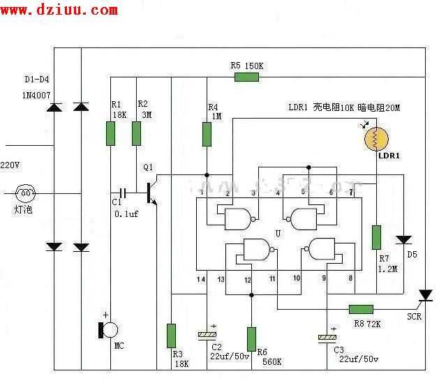
In this section, we address common issues encountered while working with the MC14001BCP integrated circuit and provide answers to frequently asked questions. Whether you’re troubleshooting circuitry or seeking clarification on its functionalities, this guide aims to streamline your experience with the component.
Identifying Common Problems
When engaging with the MC14001BCP, users may encounter various challenges that impede seamless operation. These issues often manifest in signal distortion, voltage irregularities, or circuit malfunction. Understanding the root causes behind these problems is crucial for efficient troubleshooting.
Resolving Frequently Asked Questions

Throughout your utilization of the MC14001BCP, certain inquiries may arise regarding its specifications, compatibility, or optimal usage scenarios. We compile a list of frequently asked questions to address these concerns comprehensively, offering insights and practical solutions to enhance your understanding and application of the device.