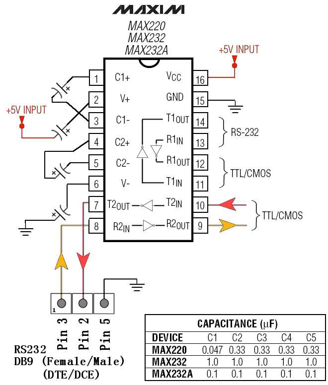
Delve into the intricacies of one of the most vital components in the world of modern electronics by exploring the fascinating world of the MAX 232 datasheet. Gain valuable insights into the inner workings of this crucial integrated circuit and discover how it revolutionizes the way electronic devices communicate with each other.
Unleash your curiosity as you embark on a captivating journey through the complex web of electrical signals and voltage levels. Learn about the ingenious design and engineering solutions employed in the MAX 232 datasheet, enabling it to bridge the gap between different voltage systems and facilitate seamless data transmission.
With the help of this insightful resource, develop a deep understanding of the intricate processes that occur within the MAX 232 datasheet, enabling it to act as a virtuoso interpreter between the worlds of TTL and RS-232 protocols. Discover how this tiny yet mighty component plays a pivotal role in empowering countless electronic devices, ranging from simple microcontrollers to advanced communications equipment.
Prepare to unravel the mysteries of this electronic powerhouse as you explore the MAX 232 datasheet. Delving into its specifications, diagrams, and application notes, you will unlock valuable knowledge and gain a competitive edge in the ever-evolving landscape of electronics. Equip yourself with the understanding to optimize your designs and harness the full potential of this remarkable component.
What is a Max 232 Datasheet?
A Max 232 Datasheet is a comprehensive technical document that provides vital information about a specific electronic component. This document serves as a valuable resource for engineers, technicians, and hobbyists who require detailed specifications and instructions for utilizing the Max 232 device in their projects.
Understanding the Purpose
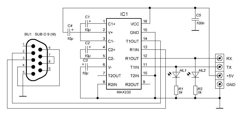
The primary objective of a Max 232 Datasheet is to offer a clear understanding of the capabilities and limitations of the Max 232 device. It aims to provide a concise overview of the component’s functionalities, electrical characteristics, recommended operating conditions, and recommended circuitry.
Navigating the Datasheet
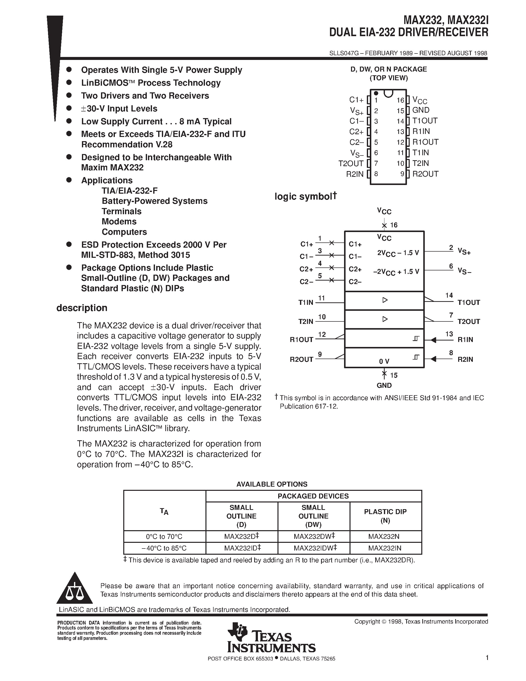
Upon accessing a Max 232 Datasheet, one will typically notice several sections that organically guide the reader through the document. These sections may include product overview, pin configuration, electrical characteristics, operating conditions, application circuits, and recommended operating guidelines.
Key information highlighted in the datasheet often includes the maximum voltage levels that the Max 232 can handle, recommended power supply values, communication protocols compatibility, and specific temperature ranges for optimal performance.
Furthermore, the datasheet may provide detailed instructions on how to establish connections between the Max 232 and other electronic components, ensuring smooth integration into a larger circuit or system. The inclusion of diagrams and tables also enhances comprehension and facilitates the successful implementation of the Max 232 device.
Overall, a Max 232 Datasheet acts as an indispensable reference, equipping individuals with the necessary knowledge to make informed decisions regarding the utilization of this electronic component. By providing a comprehensive understanding of the functionality and technical nuances, it empowers engineers, technicians, and hobbyists alike to optimize their projects and achieve reliable and efficient results.
Key Features and Specifications
The highlighted characteristics and technical details of the Max 232 integrated circuit are crucial to understanding its functionalities and potential applications. This section aims to provide an overview of the most significant features and specifications of this highly versatile component.
Enhanced Functionality
The Max 232 boasts advanced capabilities that enable seamless communication between different voltage levels in electronic systems. With its state-of-the-art design, this integrated circuit ensures reliable transmission of data signals, making it ideal for use in a wide range of applications.
By incorporating innovative technology, the Max 232 effectively resolves voltage level incompatibilities, allowing for smooth data interchange between devices operating at different voltage levels. This characteristic makes it a valuable component in various communication and interface circuits.
Precise Specifications
When it comes to technical specifications, the Max 232 offers outstanding performance and accuracy. With a wide operating voltage range and low power consumption, this IC delivers efficient and reliable operation in diverse electronic systems.
The Max 232 features multiple transmitters and receivers, ensuring seamless and bidirectional data transfer. Moreover, it supports various data formats, making it compatible with different communication protocols. Its fast data rate capability further enhances its flexibility and suitability for high-speed applications.
Additionally, the Max 232 exhibits excellent ESD protection, contributing to its robustness and long-term reliability. It is capable of withstanding high voltage levels and transient voltage spikes, ensuring the integrity of data transmission.
Overall, the Max 232 stands out as a high-performance integrated circuit, offering enhanced functionality and precise specifications. Its wide range of features and technical capabilities make it an indispensable component in numerous electronic systems and applications.
Understanding the Pinout
Understanding the pinout configuration of a device is essential for effectively utilizing its functionalities. In the case of the Max 232 datasheet, comprehending the pinout layout allows for a clear understanding of the connections and their corresponding functions without directly referring to the specific device or technical terminology.
By exploring the pinout diagram, users gain insights into the different pin configurations and their respective roles within the circuit. This knowledge aids in correctly setting up the device, establishing connections, and troubleshooting potential issues. Through a thorough understanding of the pinout, users can maximize the device’s capabilities in various applications.
- Pin 1: Voltage regulator input – This pin serves as the input for the voltage regulator, providing the necessary power for the device.
- Pin 2: Ground – This pin is connected to the ground reference, ensuring proper electrical grounding.
- Pin 3: Transmit data – This pin is responsible for transmitting data from the device.
- Pin 4: Receive data – This pin is used to receive data from external sources.
- Pin 5: External capacitor – This pin connects to an external capacitor, which helps stabilize the voltage for optimal performance.
- Pin 6: External capacitor – Similar to Pin 5, Pin 6 also connects to an external capacitor, contributing to voltage stabilization.
- Pin 7: Ground – Another ground pin that ensures proper electrical grounding.
- Pin 8: VCC – This pin provides the power supply voltage for the device.
- Pin 9: External capacitor – This pin connects to an additional external capacitor, further aiding in voltage stabilization.
- Pin 10: External capacitor – Similar to Pin 9, Pin 10 also connects to an external capacitor, enhancing voltage stabilization.
- Pin 11: Transmit data – This pin is responsible for transmitting data from external sources to the device.
- Pin 12: Receive data – This pin receives data from the device.
- Pin 13: Ground – A ground pin that contributes to proper electrical grounding.
- Pin 14: Voltage regulator output – This pin serves as the output for the voltage regulator.
- Pin 15: Voltage doubler/inverter – Depending on the circuit configuration, this pin can function as a voltage doubler or inverter.
- Pin 16: Voltage doubler/inverter – Similar to Pin 15, Pin 16 can be used as a voltage doubler or inverter, depending on the circuit requirements.
By thoroughly understanding the pinout configuration and the corresponding functions of each pin, users can confidently utilize the Max 232 datasheet in their projects, ensuring optimal performance and troubleshooting potential issues effectively.
Connection Diagrams
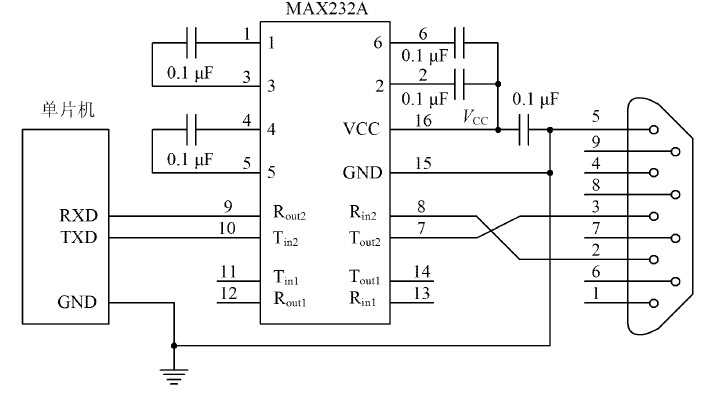
In this section, we will explore the various ways in which the Max 232 integrated circuit can be connected in different electronic circuits. These diagrams provide visual representations of the connections required for the proper functioning of the device, allowing engineers and enthusiasts to easily understand and implement the circuitry. The following descriptions will outline the key components and their connections, providing a comprehensive guide for anyone working with the Max 232 IC.
Serial Communication Interface
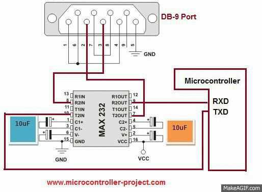
One common application for the Max 232 IC is in the serial communication interface, which allows for data exchange between devices using a serial protocol. In this diagram, the key components include the Max 232 IC, the microcontroller or computer’s UART ports, and the external devices that need to communicate. The diagram illustrates the correct connections between these components, ensuring the transmission and reception of data is efficient and accurate. Proper grounding and power connections are also highlighted, ensuring the stability of the interface.
Inverter and Level Shifter Circuits
Another important application of the Max 232 IC is in inverter and level shifter circuits. These circuits are used to convert signal levels between different voltage standards, enabling compatibility between devices operating at different voltage levels. The diagram showcases the connections between the Max 232 IC, the input and output voltage levels, and the devices that require signal conversion. Additionally, the diagram highlights the appropriate capacitors and resistors that need to be incorporated to ensure the proper functioning of the circuit.
Overall, these connection diagrams serve as invaluable resources for individuals working with the Max 232 IC. By providing clear and concise representations of the required connections for different applications, these diagrams enable efficient implementation and troubleshooting of electronic circuits utilizing this versatile integrated circuit. Careful attention to these diagrams ensures successful integration of the Max 232 IC in a wide range of electronic projects and systems.
Operating Voltage and Temperature Range
In this section, the focus will be on the acceptable range of voltage and temperature for the device under discussion. Understanding the operating conditions is crucial to ensure optimal performance and longevity of the component.
Power Supply Voltage: The device operates within a specified voltage range, which determines the maximum and minimum limits for proper functionality. It is important to adhere to this range to prevent damage to the component and avoid potential malfunctions.
Temperature Range: The operating temperature range specifies the temperature limits within which the device can function reliably. This range is crucial to consider, as extreme temperatures can affect the performance and lifespan of the component.
Considerations: It is essential to understand the voltage and temperature requirements for the device to ensure proper operation. Failure to adhere to these specifications may result in malfunctioning or decreased performance. Additionally, operating the device below or above the specified conditions may lead to irreversible damage.
Therefore, it is advisable to meticulously review and adhere to the specified operating voltage and temperature range outlined in the component’s datasheet.