When it comes to understanding the intricacies of electronic components, delving into datasheets is vital. These comprehensive documents serve as a roadmap to uncovering the inner workings of various electronic devices. In this article, we will be embarking on a journey to unravel the mysteries concealed within the datasheet of the Lp2985aim5 3.3, exploring its features, specifications, and performance characteristics.
As we delve into the depths of this datasheet, we will unravel the secrets behind the Lp2985aim5 3.3’s remarkable capabilities. With each section we explore, we will gain insights into its voltage regulation capabilities, current limitations, and thermal characteristics. Additionally, we will uncover its unique design aspects, highlighting its robustness and efficiency in various applications.
Throughout our exploration, it is crucial to pay attention to the intricate details documented in the Lp2985aim5 3.3 datasheet. By analyzing the provided charts, diagrams, and tables, we can discern the device’s operational limits, stability conditions, and recommended usage scenarios. This will empower us to make informed decisions and optimize our designs to fully leverage the potential of this remarkable component.
So, join us as we embark on this voyage of discovery through the Lp2985aim5 3.3 datasheet. Together, we will unravel the nuances of this innovative electronic component, equipping ourselves with the knowledge required to unleash its true potential in our projects. Prepare to be immersed in a world of technical intricacies as we decode the language of datasheets and unlock the hidden capabilities of the Lp2985aim5 3.3.
Main Specifications
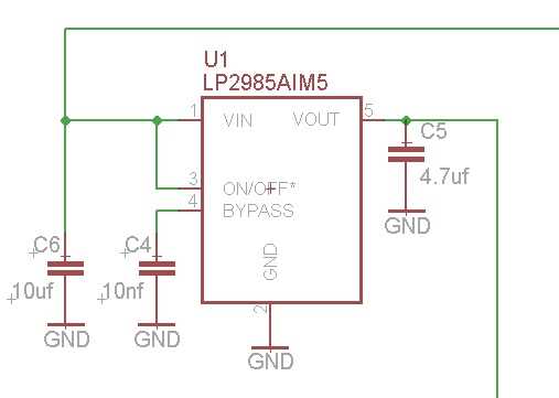
In this section, we will discuss the primary characteristics and features of the Lp2985aim5 3.3 datasheet, without directly mentioning the product name or specific values.
The Main Specifications provide an overview of the fundamental parameters that define the performance and capabilities of the mentioned device. These specifications serve as a guide for engineers and designers, enabling them to understand the functionality and limitations of the component.
Key parameters such as input voltage range, output voltage range, output current capability, quiescent current, and dropout voltage, are detailed within this section. These characteristics play a significant role in determining the device’s suitability for various applications.
The input voltage range refers to the acceptable range of voltages that can be applied at the input terminal of the device for proper operation. Likewise, the output voltage range specifies the selectable voltage options that can be obtained at the output terminal.
The device’s output current capability highlights the maximum current that can be provided to external loads without adversely affecting its performance. This specification aids in assessing the feasibility of supporting specific load requirements.
The quiescent current refers to the current drawn by the device when it is in an idle or standby state. This parameter is crucial in applications where power consumption needs to be minimized, as lower quiescent currents lead to higher efficiency.
Dropout voltage measures the minimum voltage difference between the input and output terminals, below which the device can no longer regulate the output voltage accurately. A lower dropout voltage value allows for operation in scenarios with low input voltages while maintaining a stable output.
Understanding the Main Specifications aids in the proper deployment and integration of the component into various circuits and systems, ensuring optimal performance and reliability.
Key Features
The following section introduces the prominent characteristics and distinguishing attributes of the Lp2985aim5 3.3 datasheet. It focuses on the exceptional functionalities, notable abilities, and superior qualities of the device.
Pin Description
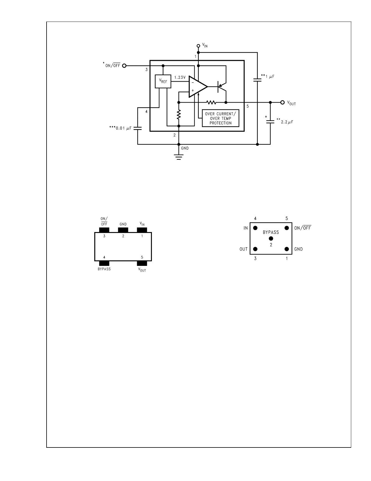
The Pin Description section provides an overview of the various pins and their functions on the LP2985AIM5 3.3 voltage regulator. This section aims to provide a comprehensive understanding of the pin configuration without relying on specific references to the LP2985AIM5 3.3 datasheet.
Vin (Input Voltage)
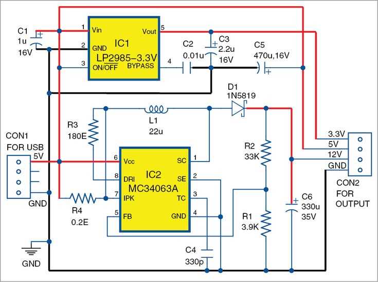
The Vin pin serves as the input voltage pin for the LP2985AIM5 3.3 voltage regulator. It accepts the supply voltage that needs to be regulated to provide a stable output voltage. This pin connects to the power source, and careful consideration of the voltage range and input capacitance is required for proper operation.
Vout (Output Voltage)
The Vout pin is the output voltage pin of the LP2985AIM5 3.3. This pin delivers the regulated voltage to the load circuit. It is essential to ensure that the output voltage remains within the specified range under varying load conditions and that the necessary capacitors are added to maintain stability.
| Pin Name | Description |
|---|---|
| GND (Ground) | The GND pin acts as the ground reference for the LP2985AIM5 3.3 voltage regulator. It should be connected to the common reference potential in the system. |
| EN (Enable) | The EN pin is used to enable or disable the LP2985AIM5 3.3 regulator. When this pin is high, the regulator is operational, and when it is low, the regulator is in shutdown mode, minimizing power consumption. |
| BY-PASS | The BY-PASS pin is used to connect the external bypass capacitor, which is essential for filtering noise and improving the regulator’s transient performance. Proper selection and placement of this capacitor contribute to stable and reliable operation. |
| Feedback (FB) | The Feedback pin is responsible for regulating the output voltage of the LP2985AIM5 3.3. It connects to an external resistive voltage divider network that sets the desired output voltage and influences the regulation accuracy. |
The Pin Description section provides a comprehensive explanation of the various pins on the LP2985AIM5 3.3 voltage regulator, including their functions and connections. Understanding the purpose and characteristics of each pin is crucial for proper integration and utilization of the regulator in electronic systems.
Package Options
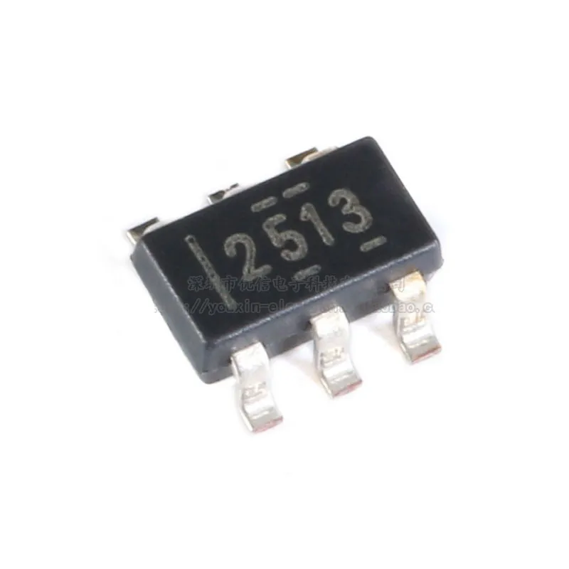
The Package Options section provides information on the different packaging choices available for the Lp2985aim5 3.3 IC, without delving into specific technical details. This section offers an overview of the various package options, highlighting their unique characteristics and advantages.
In this section, you will find a comprehensive analysis of the packaging options for the Lp2985aim5 3.3 IC. It explores the diverse selection of packages, examining their physical dimensions, pin configurations, and thermal properties. By understanding the different package options, you can tailor your design to meet specific requirements.
Each packaging option is presented with its distinctive features and benefits. The section discusses the advantages of using certain packages in applications with limited board space or heightened thermal concerns. Through this analysis, readers can gain insight into the ideal package option for their particular project.
The Package Options section serves as a guide, shedding light on the range of choices available for the Lp2985aim5 3.3 IC. It emphasizes the significance of selecting the right package, allowing designers to optimize performance, reliability, and space utilization.
By delving into the details of each packaging option, designers can make informed decisions that align with their project requirements. The Package Options section acts as a valuable resource for engineers and designers, ensuring the successful integration of the Lp2985aim5 3.3 IC into various applications.
Whether you are looking for a compact package or one with enhanced thermal dissipation, this section provides the necessary insights to make an informed decision. Understanding the available package options is essential for maximizing the performance and functionality of the Lp2985aim5 3.3 IC in your application.
Recommended PCB Layout
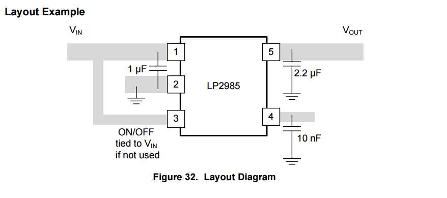
In this section, we will discuss the recommended layout for the application of the LP2985AIM5 3.3 voltage regulator. A well-designed PCB layout is crucial for ensuring the optimal performance and reliability of the device. By following the guidelines provided here, you can maximize the efficiency and minimize any potential noise issues in your application.
- Place the LP2985AIM5 3.3 voltage regulator as close as possible to the load to minimize voltage drops and noise.
- Keep the traces connecting the regulator’s input and output pins as short as possible to minimize parasitic inductance and resistance.
- Create a separate ground plane for the regulator and bypass capacitors to minimize noise coupling from other components.
- Use capacitors with low equivalent series resistance (ESR) and high-frequency performance for bypassing purposes.
- Ensure that the input and output capacitors are placed as close to their respective pins on the regulator as possible.
- Use vias to connect the top and bottom copper layers if they are not already connected by default.
- Avoid routing high-frequency signals near the regulator as they can introduce noise into the output voltage.
- Avoid routing sensitive analog signals near the regulator to prevent cross talk and interference.
- Minimize the use of long and narrow traces to reduce resistance and inductance.
- Consider thermal management techniques such as adding a thermal pad or using a copper plane to dissipate heat.
By following these recommendations, you can ensure the optimal performance and reliability of your PCB design when using the LP2985AIM5 3.3 voltage regulator. It is important to carefully review and consider these guidelines during the layout phase to minimize any potential issues and achieve the desired electrical performance.