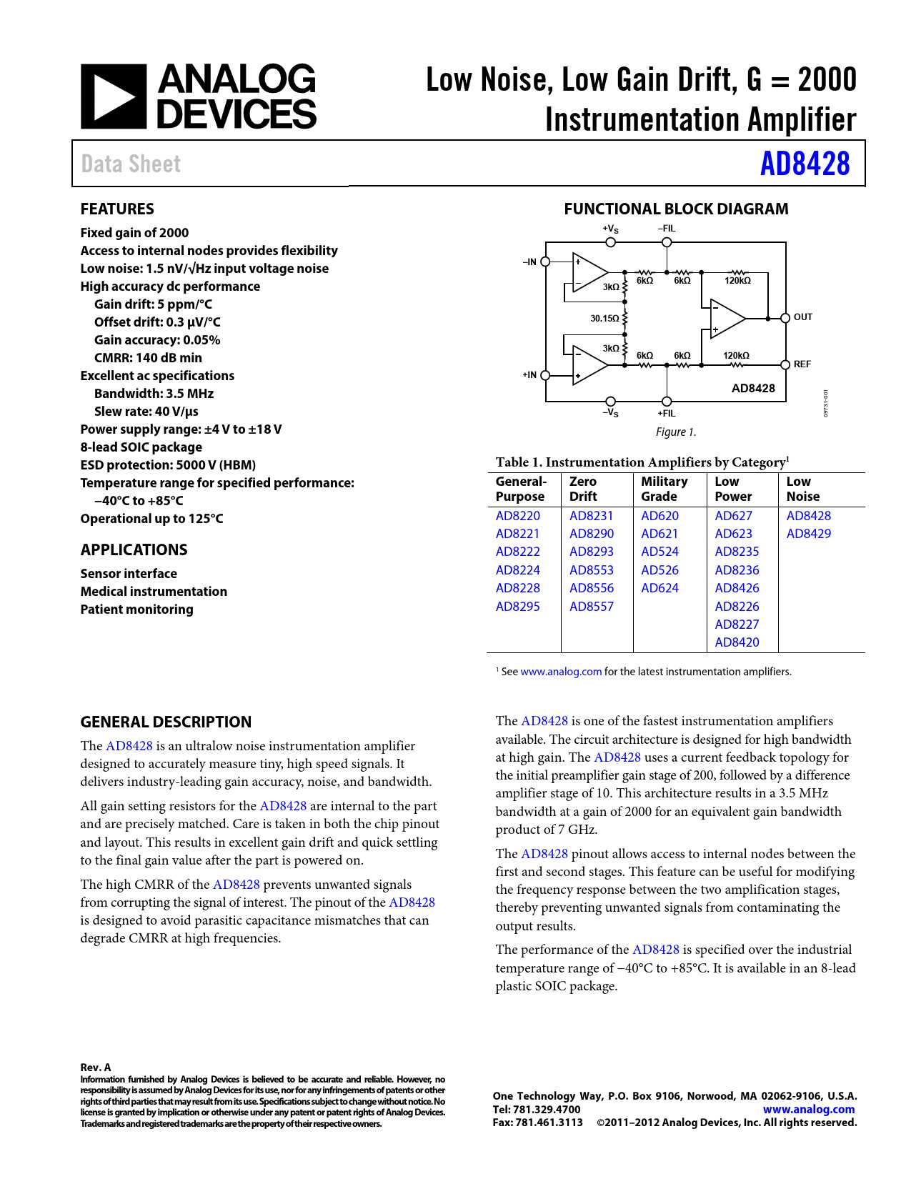
Within the intricate realm of electronics, a class of highly specialized devices has emerged, ushering in a new era of precision and reliability. These innovative components, often referred to as instrumentation amplifiers, provide engineers and designers with an invaluable tool to enhance performance, accuracy, and signal conditioning in a wide array of applications. Through a careful examination of their datasheets, one can delve into the fascinating world of these sophisticated devices, gaining valuable insights into their capabilities, specifications, and unique operational characteristics.
By delving into the intricacies of an instrumentation amplifier datasheet, one can uncover a treasure trove of crucial information about this advanced circuitry. Boldly venturing beyond the realm of conventional amplifiers, these datasheets showcase the remarkable potential inherent in these elegant electronic systems. Crucial metrics, such as gain, bandwidth, noise performance, and common-mode rejection ratio, are meticulously detailed, providing a comprehensive overview of the amplifier’s capabilities and performance under various operating conditions.
Gleaned from meticulous research and robust testing, these datasheets serve as a roadmap to successfully integrating instrumentation amplifiers into complex circuit designs. Key features, such as input and output voltage ranges, power supply requirements, and thermal considerations, are meticulously laid out, empowering engineers to make well-informed decisions when selecting and implementing these powerful devices. Armed with the information contained within these datasheets, designers can unlock the full potential of their circuits, achieving unprecedented levels of precision, accuracy, and reliability.
As the demand for precision amplification grows, navigating the intricacies of instrumentation amplifier datasheets becomes increasingly crucial. Beyond the binary realm of mere “on” and “off,” these documents serve as a bridge between the abstract concepts and the tangible reality of circuit design. By embracing the knowledge encapsulated within these datasheets and leveraging the cutting-edge technology they represent, engineers can forge a path towards the future, where precision and innovation intertwine to create the next generation of advanced electronic systems.
Understanding the Basics
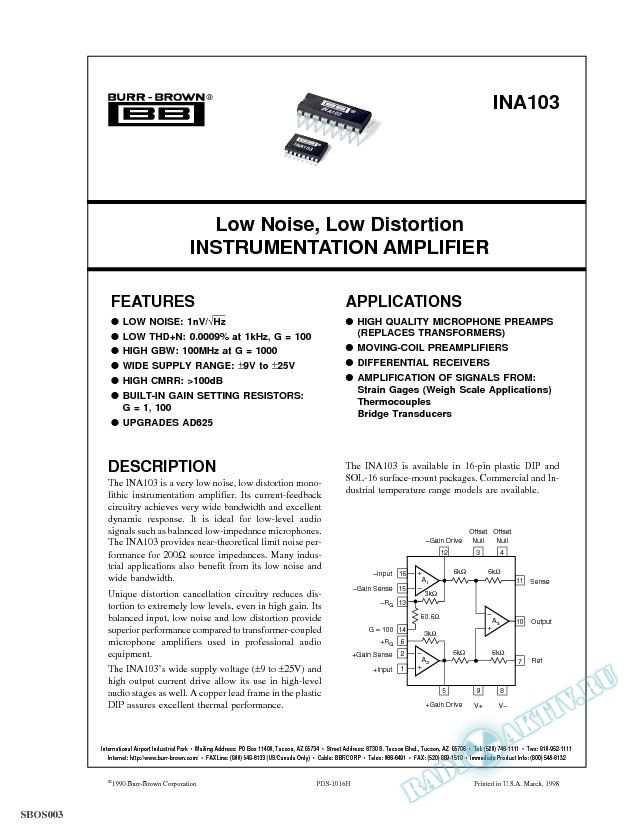
In this section, we will delve into the fundamental concepts behind the functionality and operation of an instrumentation amplifier. By gaining a solid understanding of the underlying principles, you will be better equipped to interpret and utilize the information provided in the datasheet.
The Essence of Instrumentation Amplifiers
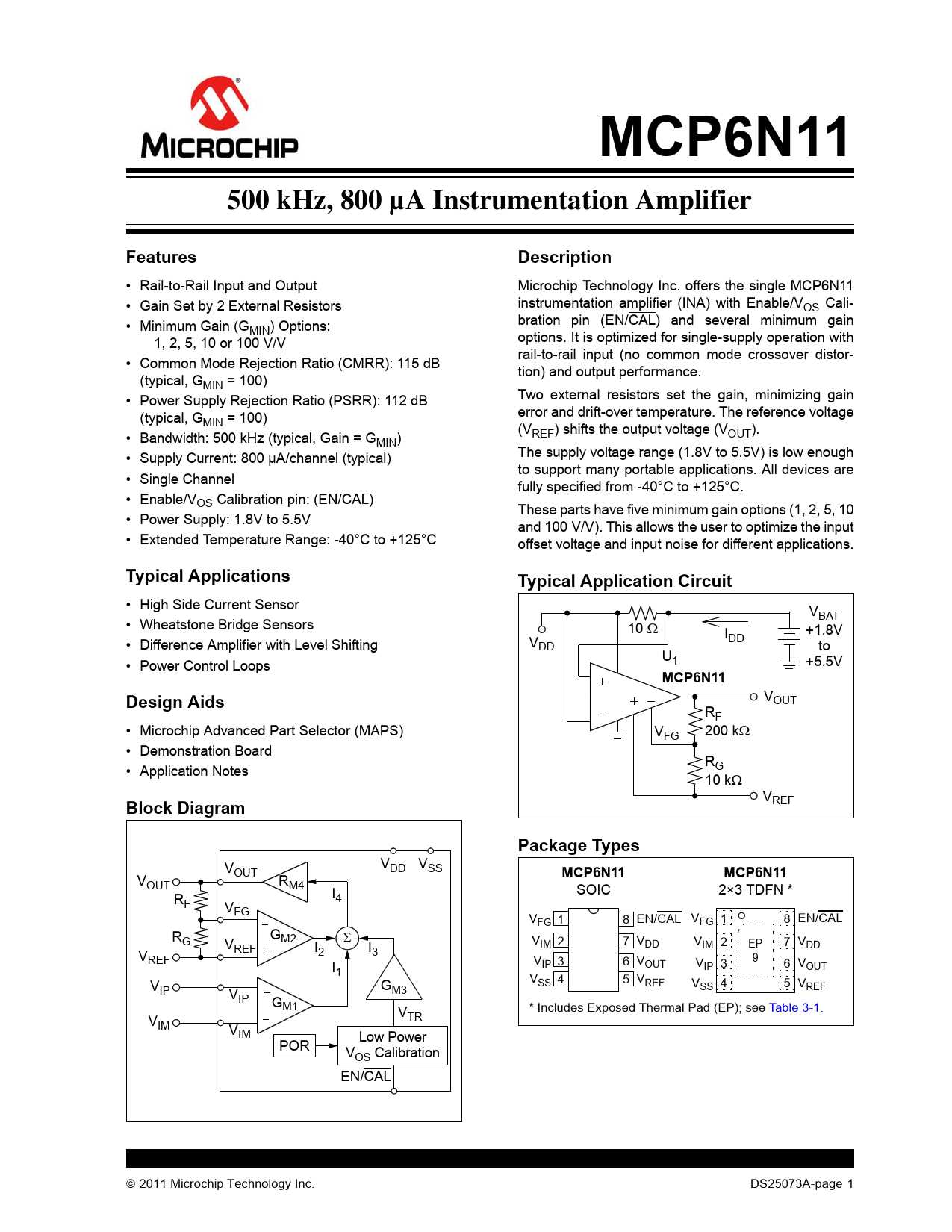
Instrumentation amplifiers, sometimes referred to as precision amplifiers, are specialized electronic devices designed to accurately measure and amplify small signals. These amplifiers play a crucial role in many applications, including scientific research, medical equipment, and industrial instrumentation.
At their core, instrumentation amplifiers consist of multiple operational amplifiers (op-amps) and precision resistors that work together to provide a high level of accuracy and performance. By carefully configuring the op-amps and using precise resistor values, instrumentation amplifiers can eliminate common-mode noise, reject interference, and provide accurate amplification of differential signals.
The Functionality of Instrumentation Amplifiers
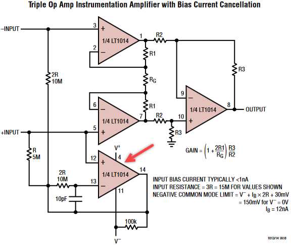
Instrumentation amplifiers excel in scenarios where the desired signal is very weak or buried within noise. They achieve this by amplifying the differential voltage between two input signals, while actively suppressing any noise or interference that is common to both inputs.
Through the use of input buffering, gain adjustment, and output buffering, instrumentation amplifiers are able to provide high gain with excellent common-mode rejection ratio (CMRR) and low total harmonic distortion (THD) characteristics. This makes them ideal for precise measurements where accuracy and signal integrity are of utmost importance.
Furthermore, instrumentation amplifiers often offer features such as adjustable gain, low input offset voltage, and rail-to-rail output swing, making them versatile and adaptable to various applications and signal conditions.
Key Specifications and Performance Parameters
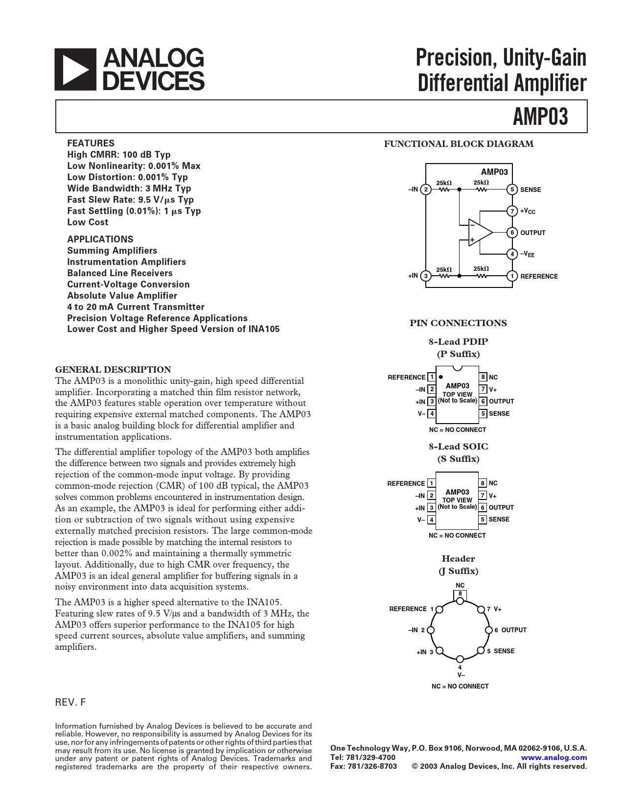
In this section, we will explore the essential specifications and performance parameters that are crucial in evaluating the capabilities and quality of an instrumentation amplifier datasheet. By examining these factors, you can gain a deeper understanding of the device’s functionality and determine its suitability for your specific application.
Signal-to-Noise Ratio (SNR): This parameter indicates the level of desired signal compared to the background noise present in the amplified output. A higher SNR value signifies better noise rejection and a cleaner signal, ensuring accurate and reliable data acquisition.
Gain Accuracy: The gain accuracy refers to the amplifier’s ability to precisely amplify the input signal at the desired gain value. It is important to ensure that the device can maintain a consistent and accurate amplification to minimize errors in measurements or signal processing applications.
Bandwidth: The bandwidth defines the range of frequencies over which the amplifier can accurately amplify the input signal. It is crucial to select an instrumentation amplifier with a bandwidth suitable for your application’s frequency range to avoid distortion or loss of information.
Common Mode Rejection Ratio (CMRR): CMRR measures the amplifier’s ability to reject common-mode signals, which are unwanted signals that appear on both input terminals. A high CMRR value indicates a greater ability to suppress common-mode interference, resulting in a cleaner output signal.
Input Impedance: The input impedance represents the resistance that the amplifier presents to the signal source. A higher input impedance ensures minimal loading of the source, preventing signal degradation and maintaining the integrity of the input signal.
Power Supply Rejection Ratio (PSRR): PSRR measures the amplifier’s resistance to variations in the power supply voltage. A higher PSRR value indicates a greater ability to reject power supply noise, ensuring stable and accurate amplification regardless of power supply fluctuations.
Temperature Range: The operational temperature range specifies the minimum and maximum temperatures within which the amplifier can reliably operate. It is crucial to choose an instrumentation amplifier with a temperature range suitable for your application’s operating conditions to ensure consistent performance and longevity.
Package Type: Different amplifiers may be available in various package types, such as surface mount or through-hole, to accommodate different mounting options and assembly techniques. Selecting the appropriate package type is essential to ensure compatibility with your system design and manufacturing processes.
By considering and evaluating these key specifications and performance parameters, you can make an informed decision in selecting the most suitable instrumentation amplifier for your application needs.
Interpreting Graphs and Application Examples
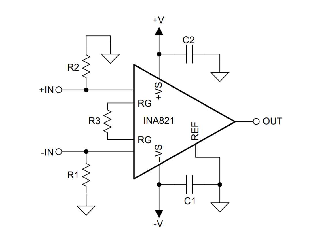
In this section, we will explore the visual representations and practical uses of a device commonly employed in electronic circuits. By understanding how to interpret graphs and examine real-world scenarios, we can gain valuable insights into the functionality and application of this innovative component.
Graphs provide a graphical representation of the performance characteristics and behavior of the device, allowing us to observe and analyze important parameters. These visual aids present data in a clear and concise manner, allowing for easier comprehension and comparison.
In addition to graphs, real-life application examples further enhance our understanding of the device’s versatility and suitability for various scenarios. By examining practical implementations, we can identify the specific advantages and benefits provided by this component in different contexts.
Through the interpretation of graphs, we can determine the device’s frequency response, gain, input/output characteristics, and other key properties. These insights enable us to make informed decisions when selecting and implementing the component in our circuits.
Furthermore, by exploring application examples, we can discover how the device excels in signal conditioning, sensor amplification, medical instrumentation, and other essential areas. By understanding the real-world applications, we can unleash the full potential of this component and utilize it effectively in our projects.
Overall, this section aims to provide a comprehensive understanding of the device’s performance through the interpretation of graphs and through practical application examples. By delving into these aspects, we can gain a deeper appreciation for the capabilities and potential of this essential electronic component.