Unlocking the potential of contemporary electronics often hinges on the intricate dance of components working in concert, each playing a crucial role in the symphony of functionality. Among these vital players lies a particular unit that serves as the silent conductor, orchestrating the flow of power with precision and finesse.
Delving into the heart of modern circuitry unveils a cornerstone element, one whose significance belies its unassuming appearance. This pivotal component, akin to the silent architect behind a grand structure, crafts the pathways through which energy courses, ensuring harmony and efficiency.
As engineers and enthusiasts alike navigate the labyrinth of technical specifications and schematics, they encounter a linchpin whose mastery dictates the fate of electrical systems. Its nuances, often overlooked by the uninitiated, hold the key to optimized performance and reliability.
Understanding the Ina210 Documentation
Delving into the intricacies of the Ina210 documentation involves navigating through a labyrinth of technical insights and operational parameters. This section aims to shed light on deciphering the wealth of information presented in this comprehensive resource, guiding users towards a profound comprehension of the device’s functionality and specifications.
Deciphering Operational Characteristics
Within the documentation, detailed descriptions elucidate the operational characteristics of the device, delineating its performance metrics and operational boundaries. By dissecting these descriptions, users can glean insights into the device’s behavior under various conditions, facilitating informed decision-making during application design and implementation.
Interpreting Electrical Specifications
Embedded within the documentation are a plethora of electrical specifications, serving as a roadmap to the device’s capabilities and limitations. These specifications encompass parameters such as voltage ranges, current sensing accuracy, and power dissipation characteristics. By deciphering these specifications, users can effectively gauge the device’s suitability for specific applications, ensuring optimal performance and reliability.
| Parameter | Description |
|---|---|
| Input Voltage Range | The range of voltages over which the device can accurately sense current. |
| Common-Mode Rejection Ratio (CMRR) | Measure of the device’s ability to reject common-mode signals. |
| Bandwidth | The range of frequencies over which the device can accurately measure current. |
By leveraging these insights and utilizing the provided tables and graphs, users can unlock the full potential of the Ina210, harnessing its capabilities to address a myriad of application requirements with precision and efficacy.
Key Specifications and Features
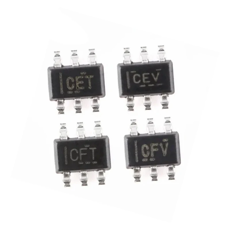
Exploring the essential characteristics and functionalities of this electronic component, this section delves into the core specifications and standout features that define its performance and utility. Highlighting its capabilities and distinguishing attributes, this segment offers insights into the fundamental aspects critical for understanding its application and integration.
Performance Metrics
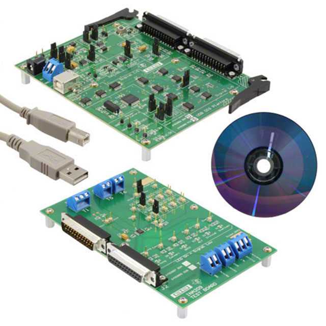
Performance Metrics: Evaluating the operational parameters and performance benchmarks, this device showcases notable metrics that underpin its functionality. From precision to efficiency, each metric contributes to its overall performance, ensuring reliability and accuracy in diverse applications.
Key Features
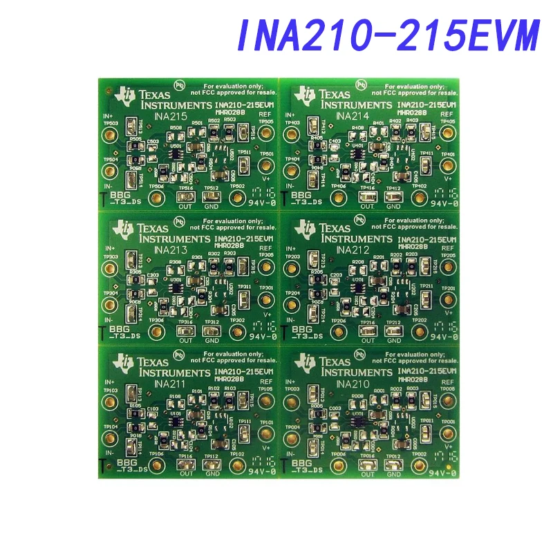
Key Features: Unveiling the unique functionalities and characteristics, this component boasts a range of features essential for its intended usage. From advanced technologies to innovative designs, these features distinguish it from alternatives, offering versatility and effectiveness in various scenarios.
Application Circuit Design Guidelines
Optimizing the operational performance of the integrated circuit under discussion involves meticulous attention to circuit design principles. Effective utilization of the device necessitates a comprehensive understanding of its operational parameters and the intricacies of the surrounding circuitry. This section elucidates fundamental guidelines to facilitate the seamless integration of the device within diverse application circuits.
Consideration of voltage levels, signal integrity, and power management forms the cornerstone of robust application circuit design. Ensuring proper voltage regulation and noise suppression mechanisms is imperative to mitigate potential signal degradation and enhance overall system reliability. Attention to detail in power distribution layouts and component selection is pivotal in achieving optimal performance across varying operational conditions.
Furthermore, judicious component placement and routing techniques are paramount in minimizing parasitic effects and maximizing signal integrity. Strategic placement of critical components and careful consideration of trace routing geometries contribute significantly to the reduction of parasitic capacitance and inductance, thereby preserving signal fidelity and integrity. This meticulous approach to circuit layout serves to enhance the device’s responsiveness and stability in real-world applications.
Additionally, adherence to recommended layout practices and thermal management strategies is indispensable in ensuring the device operates within specified temperature ranges and sustains long-term reliability. Implementation of adequate thermal dissipation mechanisms, such as heat sinks and proper PCB layout techniques, is essential for preventing thermal-induced performance degradation and prolonging the operational lifespan of the integrated circuit.
In summary, meticulous attention to circuit design fundamentals, encompassing voltage regulation, signal integrity preservation, and thermal management, is essential for unlocking the full potential of the integrated circuit in diverse application scenarios. By adhering to these guidelines and leveraging best practices in circuit design, engineers can optimize system performance, enhance reliability, and expedite time-to-market for their innovative solutions.
Performance Evaluation and Testing Considerations
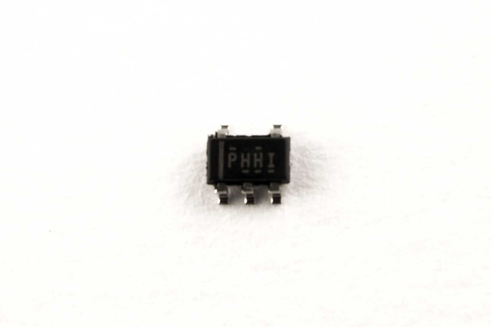
When assessing the efficacy and reliability of electronic components, it becomes imperative to delve into the intricacies of their operational performance and the methodologies employed in their testing. This section aims to elucidate key considerations pertinent to evaluating the functionality and performance of electronic components, steering clear of specific nomenclature to ensure a broad applicability of insights.
Understanding Operational Parameters
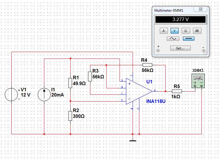
Operational parameters encompass a spectrum of characteristics that delineate the behavior of electronic components under varying conditions. These parameters encompass aspects such as efficiency, precision, and stability, each wielding significant influence over the component’s performance in diverse applications.
Evaluating Reliability and Durability
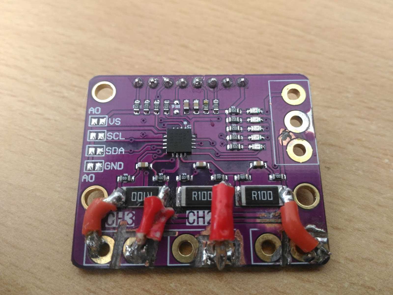
Amidst the pursuit of optimal performance, reliability and durability emerge as paramount concerns. Rigorous testing regimes are imperative to ascertain the robustness of components under stress conditions, gauging their ability to withstand prolonged usage without succumbing to degradation or failure.