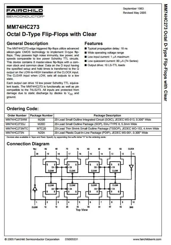
Delve into the intricate blueprint that powers modern marvels. Discover a labyrinth of circuits and pathways, each meticulously crafted to orchestrate a symphony of function and form. At the heart of innovation lies a document that serves as the guiding light, unveiling the secrets of electronic mastery.
Embark on a journey of discovery as we unravel the enigmatic essence of the Hc273 blueprint. Traverse through a landscape of symbols and diagrams, where every line holds the promise of a new revelation. Beyond the mere arrangement of components lies a narrative of ingenuity, waiting to be deciphered by those who dare to explore.
Peel back the layers of complexity to reveal the raw essence of technological prowess. Each word penned within the sacred manuscript carries the weight of possibility, offering a glimpse into the realm of endless innovation. From abstract concepts to tangible realities, the Hc273 blueprint stands as a testament to the boundless creativity of the human mind.
Understanding the Hc273 Datasheet: Key Specifications and Features
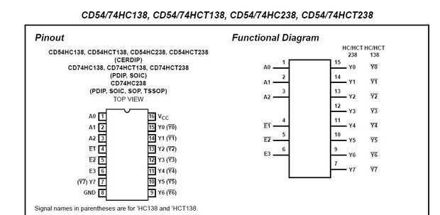
In the realm of electronic components, comprehending the intricacies of a device is pivotal for optimal utilization. Exploring the detailed documentation of the Hc273 unveils crucial insights into its functionality, performance, and integration potential. This section delves into essential specifications and notable features, providing a comprehensive overview essential for informed decision-making and effective implementation.
Functional Overview
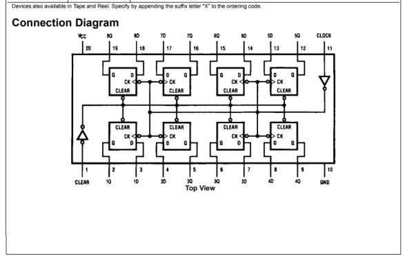
Before delving into specifics, it’s imperative to grasp the functional essence of the Hc273. Understanding its core operations elucidates its significance within circuitry and facilitates seamless incorporation into diverse applications. This overview encapsulates the device’s fundamental purpose and its role within electronic systems.
Key Specifications
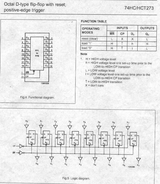
Embarking on a journey through the datasheet, one encounters a myriad of numerical values and technical jargon defining the Hc273’s performance parameters. These specifications serve as quantitative benchmarks, delineating its capabilities in terms of speed, voltage tolerance, power consumption, and more. An in-depth comprehension of these figures empowers engineers to tailor their designs to precise requirements and optimize overall system performance.
Exploring the Functionalities and Pinout Configuration
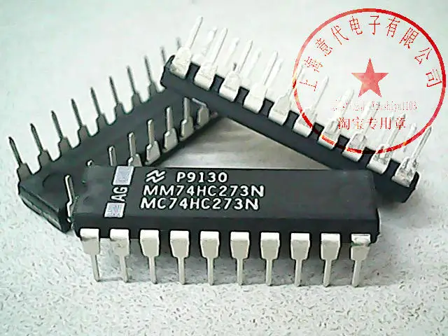
In this section, we delve into the intricate functionalities and pinout configuration of the component under examination. Through a detailed exploration, we uncover the diverse array of operations and connections inherent within.
Functionality Overview
Embark on a journey through the myriad functionalities of the component, unraveling its capabilities and operational nuances. From basic functions to complex operations, each facet contributes to the comprehensive understanding of its utility.
Pinout Configuration
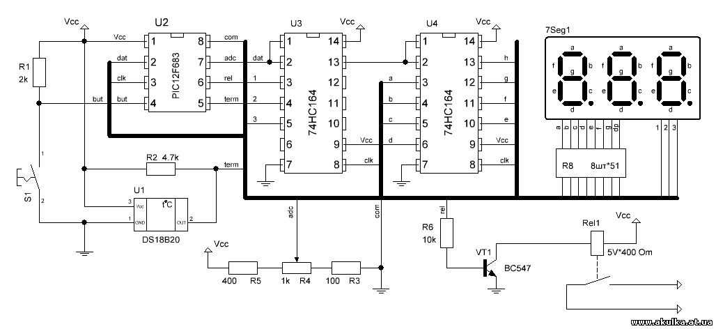
Discover the intricate layout of pins and their respective configurations, mapping out the connectivity landscape of the component. Through a systematic examination, each pin’s role and significance become elucidated, paving the way for seamless integration and utilization.
| Pin Number | Description | Functionality |
|---|---|---|
| 1 | Input A | Accepts input signal A |
| 2 | Input B | Accepts input signal B |
| 3 | Input C | Accepts input signal C |
| 4 | Input D | Accepts input signal D |
| 5 | Clear | Clears the output |
| 6 | Clock | Input for clock signal |
| 7 | Output | Output signal |
| 8 | GND | Ground connection |
Interpreting Timing Diagrams and Electrical Characteristics
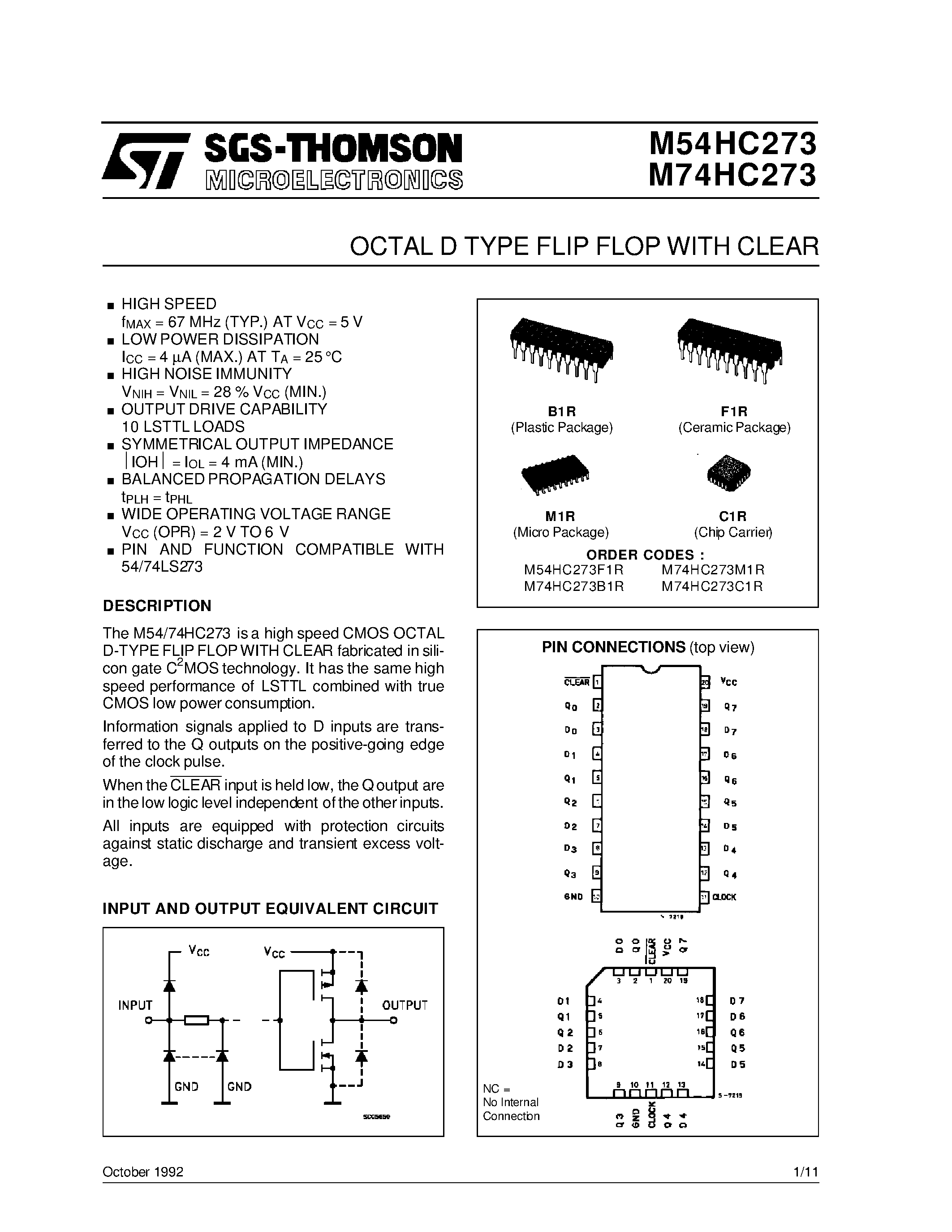
Understanding the intricacies of timing diagrams and electrical characteristics is paramount in navigating the specifications of integrated circuits. These graphical representations provide vital insights into the behavior and performance of electronic components, offering a comprehensive view of signal timing, transitions, and electrical parameters.
Deciphering Timing Diagrams
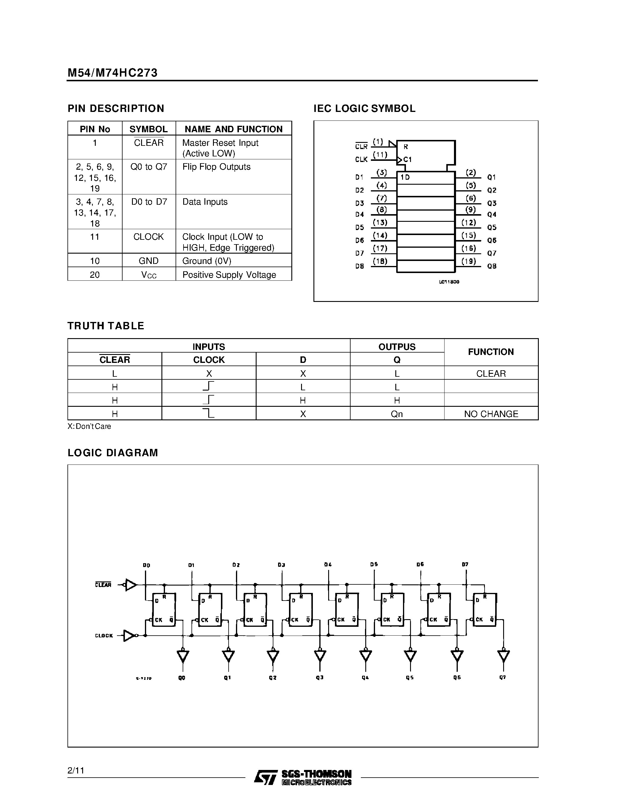
Timing diagrams serve as visual aids to illustrate the timing relationships between various signals within a digital system. By analyzing these diagrams, engineers can discern crucial information such as signal propagation delays, setup and hold times, clock transitions, and data valid windows. Each element of a timing diagram contributes to the overall understanding of signal integrity and synchronization within the system.
Signal transitions are depicted through waveform traces, showcasing the progression of signals over time. Rising and falling edges denote state changes, while the duration between transitions reveals timing constraints and signal stability.
Analyzing Electrical Characteristics
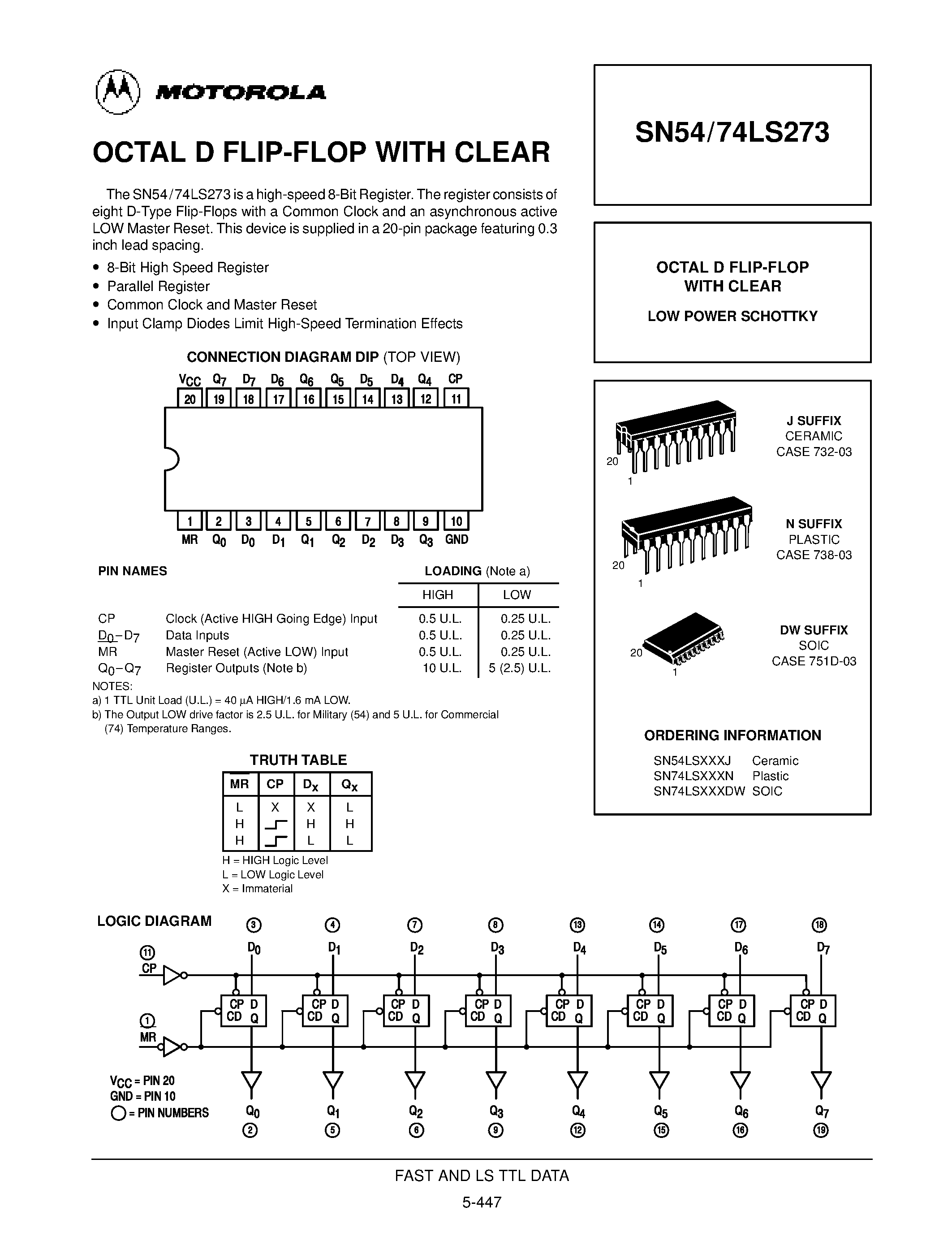
Electrical characteristics encompass a spectrum of parameters that define the operational behavior and limitations of electronic components. These include voltage levels, current requirements, noise margins, and power consumption. By interpreting these characteristics, engineers can ensure compatibility, reliability, and optimal performance in circuit design and implementation.
Understanding voltage thresholds is fundamental in determining signal compatibility and noise immunity. Threshold levels dictate the point at which a signal is recognized as a logical high or low, influencing the overall reliability of data transmission and reception.
Application Notes and Considerations for Integration
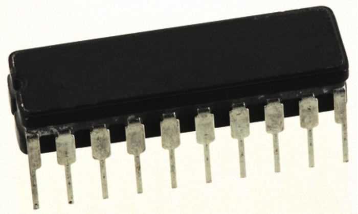
When assimilating electronic components into a system, it’s vital to delve beyond the surface specifications and delve into the intricacies of integration. This section serves as a guidepost for navigating the labyrinth of considerations, providing insights and strategies for seamless amalgamation.
Understanding the interplay between diverse components is paramount. Cohesion hinges on meticulous attention to detail, where each component’s function harmonizes with others like instruments in an orchestra, orchestrating a symphony of efficiency.
Integration entails more than mere physical connection; it demands comprehension of signal propagation, power distribution, and compatibility nuances. In essence, it’s a ballet of electrical choreography, where missteps can lead to discord rather than harmony.
Moreover, temporal considerations weigh heavily in the integration equation. Future scalability, technological obsolescence, and adaptability must be factored into the integration blueprint, ensuring longevity amidst the relentless march of progress.
Finally, while datasheets provide a foundational understanding, real-world integration often unveils nuances not captured in technical documentation. Thus, a holistic approach, amalgamating theoretical knowledge with empirical wisdom, is indispensable for successful integration endeavors.