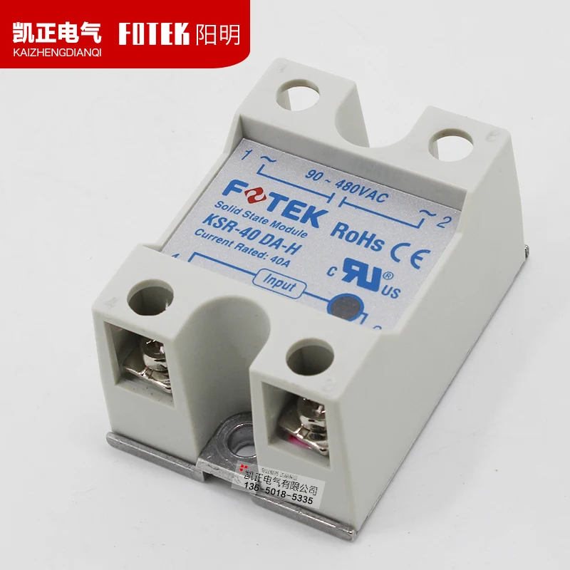
Unlocking the potential of cutting-edge electrical components demands a meticulous understanding of their technical specifications and performance parameters. In the realm of modern electronics, delving into the intricacies of component datasheets serves as a gateway to harnessing their capabilities effectively. These documents, akin to blueprints of innovation, encapsulate crucial details about the operation, limitations, and application nuances of diverse electronic elements.
Embarking on an exploration of a particular datasheet, such as that of a certain semiconductor switch, offers a voyage into the heart of its functionality. Through detailed analyses and comprehension of the provided information, engineers and enthusiasts alike gain insights into the inner workings of the component. It’s not merely a documentation of specifications but a roadmap to leveraging its potential within circuits and systems.
Within these pages lie the keys to unlocking the full spectrum of possibilities that the component offers, from its electrical characteristics to its thermal behavior and mechanical considerations. A skilled reader can discern not just the nominal ratings but also delve into the fine print, understanding transient responses, protection features, and environmental tolerances. Such comprehension is pivotal in ensuring optimal integration and performance in real-world applications.
The Basics of Understanding Fotek SSR Documentation
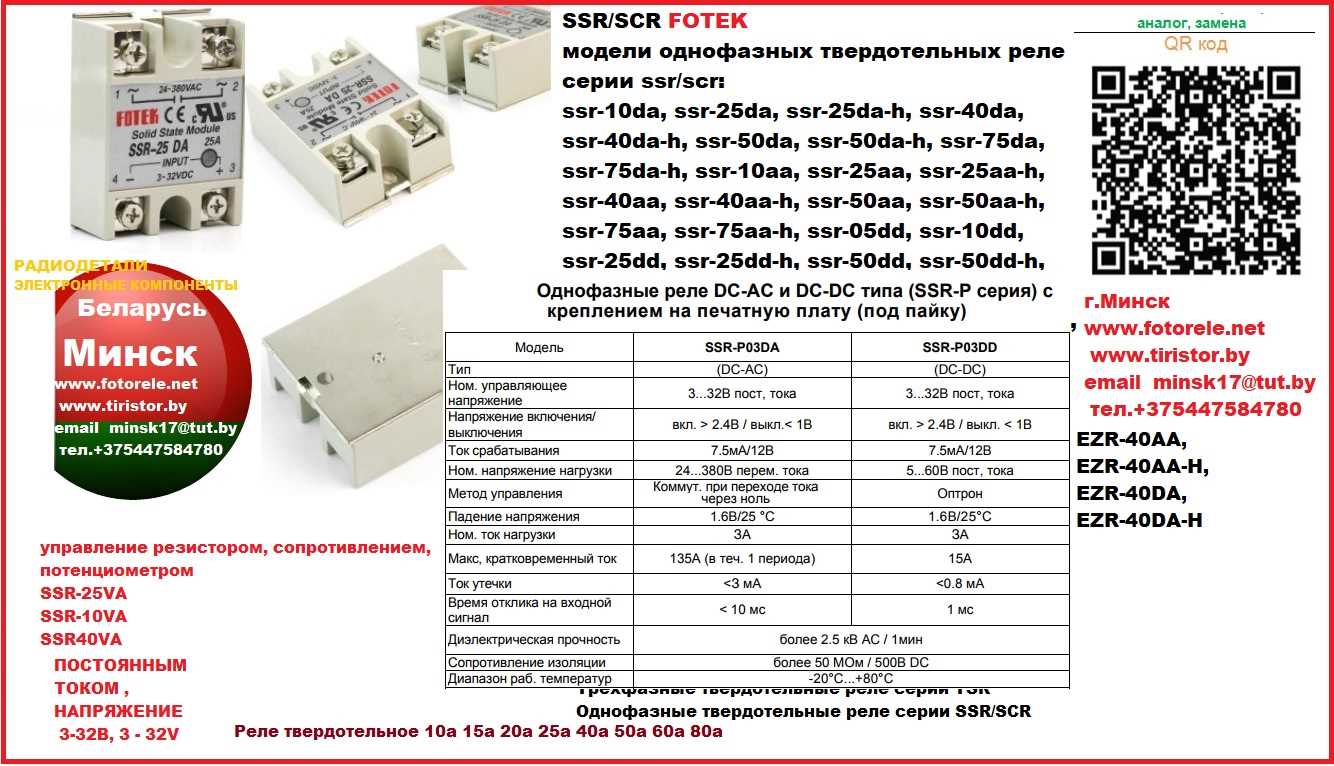
When delving into the intricacies of Fotek’s offerings in the realm of solid-state relay technology, it’s paramount to navigate through the documentation with clarity and comprehension. In this section, we’ll elucidate fundamental principles and elements integral to interpreting and harnessing the potential encapsulated within Fotek’s SSR datasheets.
1. Key Specifications and Performance Metrics
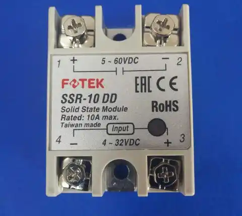
Within the annals of Fotek’s SSR documentation, vital specifications and performance metrics serve as guiding beacons for discerning engineers and enthusiasts alike. These metrics encapsulate the relay’s capabilities, including load voltage and current ratings, input control voltage, response time, and insulation resistance. Understanding these parameters is pivotal in aligning the relay with specific application requirements.
2. Functional Diagrams and Schematic Representations
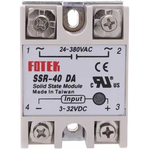
Embedded within Fotek’s SSR datasheets are functional diagrams and schematic representations, offering visual insights into the relay’s operational anatomy and connectivity nuances. These diagrams delineate input and output terminals, control circuitry, and isolation barriers, furnishing a comprehensive blueprint for integration into diverse electronic systems.
- Explore Load Compatibility: Investigate compatibility with various load types, such as resistive, inductive, or capacitive, to ascertain optimal relay selection.
- Probe Thermal Considerations: Delve into thermal management aspects, including heat dissipation capabilities and temperature limits, to preempt overheating issues.
- Scrutinize Mounting and Mechanical Dimensions: Assess mounting options and mechanical dimensions to ensure seamless integration within spatial constraints.
By delving into these foundational aspects of Fotek SSR datasheets, enthusiasts and professionals alike can navigate the labyrinth of technical documentation with confidence, unlocking the full potential of solid-state relay technology.
Understanding Technical Specifications
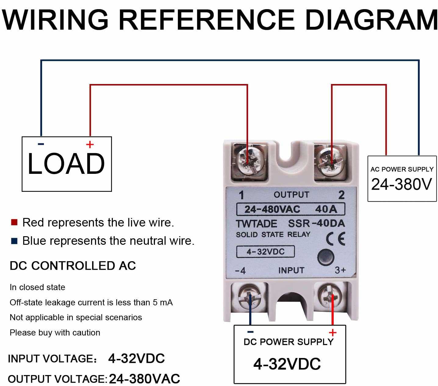
Delving into the intricacies of product documentation provides a roadmap for comprehending the functionality and capabilities of electronic components. In this section, we embark on a journey through the labyrinth of technical specifications, deciphering the language that delineates the performance and characteristics of devices.
- Performance Metrics: These parameters elucidate the operational capabilities of the component, shedding light on its efficiency, speed, and reliability.
- Electrical Characteristics: Within this domain lie details concerning voltage ratings, current capacities, and impedance, crucial for understanding the electrical behavior of the component within a circuit.
- Environmental Considerations: Exploring this aspect unveils information regarding operating temperature ranges, humidity tolerance, and resistance to external factors, vital for determining the component’s suitability for diverse environments.
- Connection and Mounting: Understanding how the component interfaces with external systems and the methods by which it can be integrated into circuits are fundamental aspects covered under this category.
- Safety and Compliance: This section delineates adherence to regulatory standards, ensuring that the component meets specified safety protocols and complies with relevant certifications.
By dissecting and comprehending the technical specifications, engineers and enthusiasts alike gain a deeper understanding of the capabilities and limitations of electronic components, empowering informed decision-making and fostering innovation.
Interpreting Electrical Characteristics
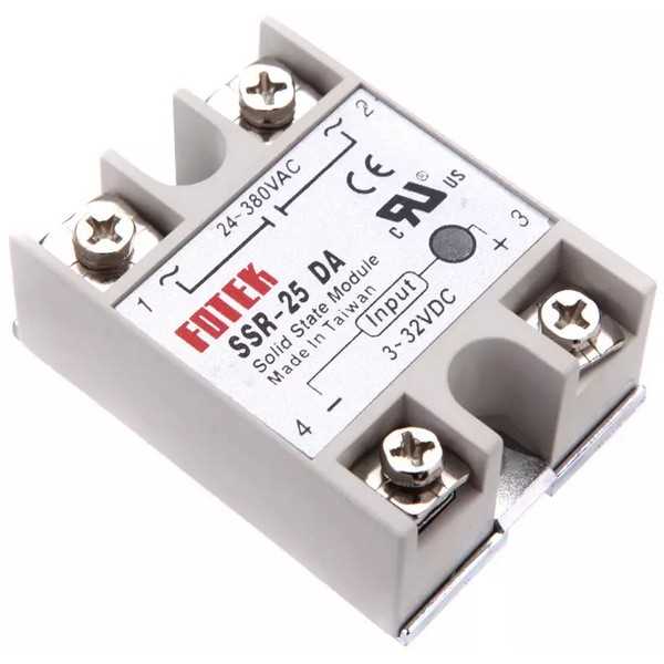
Understanding the technical specifications of electronic components is crucial for effective utilization and integration into circuits. In this section, we delve into deciphering the intricate electrical attributes presented in the documentation. By comprehending these parameters, engineers can make informed decisions regarding component selection and system design.
- Operating Voltage Range: This parameter delineates the span within which the component can function reliably. It signifies the permissible range of input voltages without compromising performance or longevity.
- Input Current: Describes the magnitude of current required to activate the device. It offers insights into the electrical demands imposed on the driving circuitry.
- Output Voltage: Indicates the voltage level at which the component switches states. It elucidates the electrical potential at the output terminals under specified conditions.
- Switching Time: Refers to the duration taken by the component to transition between states upon receiving an input signal. It elucidates the responsiveness and efficiency of the device in altering its conductive state.
- Isolation Voltage: Signifies the maximum voltage that can be applied across the input and output terminals without causing electrical breakdown. It ensures galvanic isolation between the control and load circuits.
By discerning these electrical characteristics, engineers can meticulously evaluate the compatibility and performance of the component within the intended application. Each parameter encapsulates vital information essential for seamless integration and optimal functionality.
Deciphering Application Notes in Fotek SSR Documentation
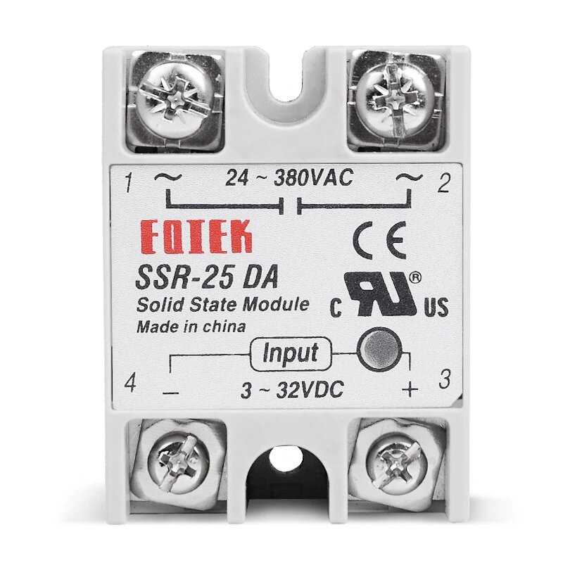
Understanding the intricacies of utilizing Fotek’s solid-state relay technology involves delving into the comprehensive application notes provided within the documentation. These notes serve as invaluable guides, offering insights into optimal deployment strategies, potential pitfalls, and nuanced operational considerations.
| Section | Content |
|---|---|
| 1. Operational Guidelines | Explore the recommended operating parameters for Fotek SSRs, including voltage and current specifications, temperature ranges, and environmental conditions. |
| 2. Load Compatibility | Learn about the types of loads compatible with Fotek SSRs, such as resistive, inductive, or capacitive loads, and understand the implications for performance and longevity. |
| 3. Wiring and Installation | Gain insights into proper wiring techniques, terminal configurations, and installation best practices to ensure safe and efficient SSR integration into electrical systems. |
| 4. Troubleshooting Tips | Discover common issues encountered during SSR operation and strategies for diagnosing and resolving these challenges effectively. |
| 5. Application Examples | Explore real-world scenarios illustrating the diverse applications of Fotek SSRs across various industries, providing inspiration and guidance for custom deployments. |
By deciphering these application notes, users can harness the full potential of Fotek solid-state relay technology, optimizing performance, reliability, and safety in their electrical systems.
Implementing Solid-State Relays in Various Circuits
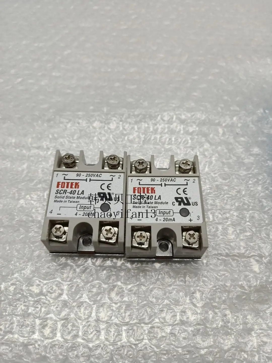
In this section, we explore the application of solid-state relays (SSRs) across a spectrum of circuits, showcasing their versatility and adaptability in different electrical setups. From simple switching circuits to more complex configurations, SSRs offer reliable control and isolation without the need for mechanical contacts.
1. Basic Switching Circuits
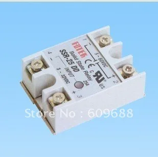
At its core, the SSR functions as a switch in electronic circuits, facilitating the control of power flow without physical contact. In basic switching circuits, SSRs find application in turning on/off lights, heaters, motors, and other electrical devices. These circuits often involve a power source, a load, and a control signal, with the SSR acting as the intermediary between the control and load circuits.
2. Temperature Control Systems
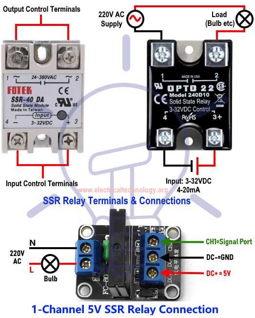
SSRs play a crucial role in temperature control systems where precision and reliability are paramount. By interfacing SSRs with temperature sensors and feedback mechanisms, engineers can design intricate heating or cooling systems for industrial processes, HVAC (Heating, Ventilation, and Air Conditioning) units, incubators, and more. SSRs offer rapid response times and precise temperature regulation, enhancing efficiency and safety in such systems.
| Circuit Type | Key Features |
|---|---|
| Basic Switching | Simple control, suitable for various loads |
| Temperature Control | Precision regulation, rapid response |