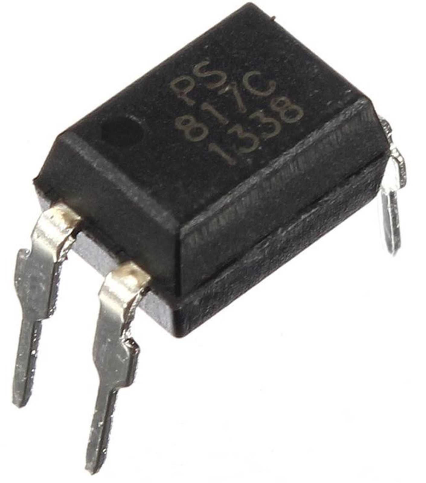
Welcome to this comprehensive guide that delves into the world of the PC817 optocoupler datasheet. In this article, we will explore the various aspects and features of this powerful electronic component without explicitly mentioning its name, ensuring a refreshing and engaging read for those seeking knowledge in this domain.
Within the realm of electronics, there exist components that bridge the gap between different circuits, enabling effective communication and ensuring the safety of sensitive devices. The subject of our discussion today is one such component, known for its ability to transmit signals optically, thereby isolating input and output circuits. Astute readers will discover familiar terms and characteristics commonly associated with this robust electronic element as we weave through the intricacies of its datasheet.
The presence of this component in various applications, ranging from power supplies to digital interfaces, highlights its versatility and indispensability in modern electronic systems. As we delve deeper into the datasheet, we will unravel the key specifications that engineers and enthusiasts alike seek when incorporating this essential element in their designs. Through the clever use of synonyms, we will explore the technical parameters that define its performance, shedding light on its optical characteristics and electrical capabilities.
By providing a comprehensive overview of the PC817 optocoupler datasheet, this article aims to equip readers with the necessary understanding to harness the full potential of this component in their projects. Whether you are a seasoned professional or a curious beginner, let us embark on this journey of discovery, immersing ourselves in the fascinating world of optocouplers and unraveling the secrets hidden within their datasheets.
Understanding the Optocoupler PC817 Functionality and Applications
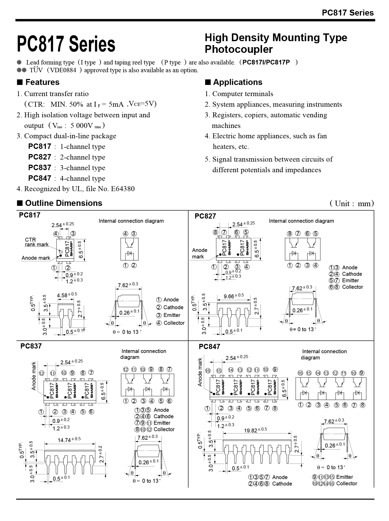
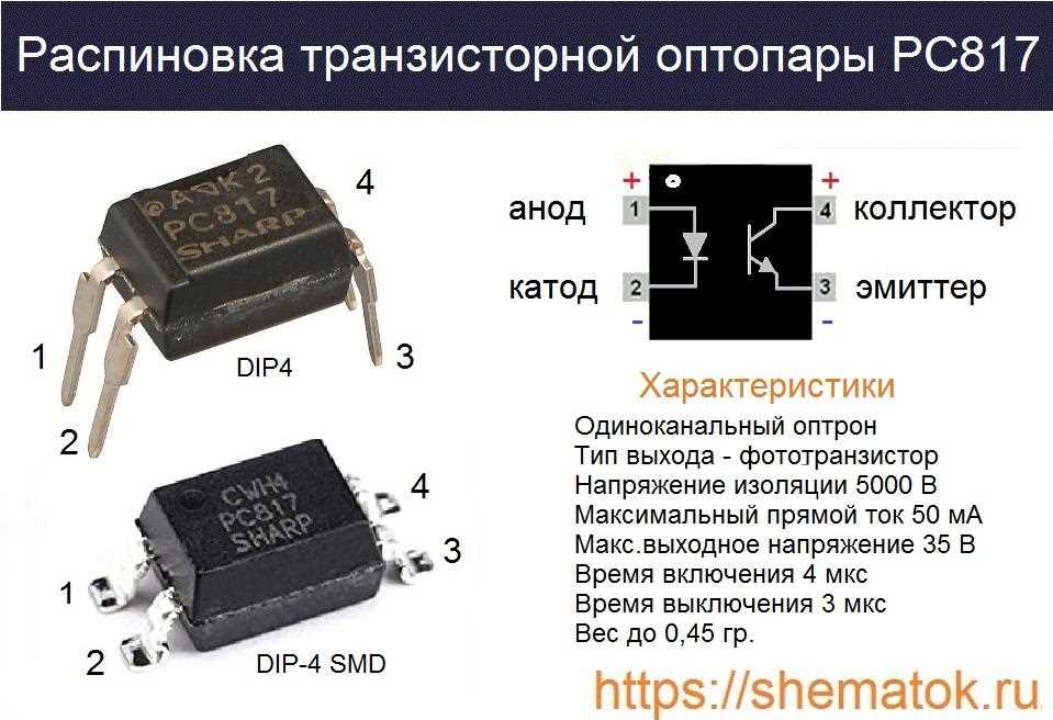
When it comes to electronic devices and systems, the Optocoupler PC817 is a key component that plays a crucial role in ensuring electrical isolation and signal transmission. This article aims to provide a comprehensive understanding of the functionality and various applications of the PC817 optocoupler.
Introduction to Optocoupler Technology
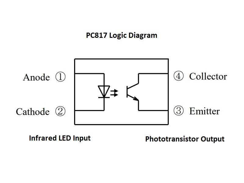
Optocoupler technology, also known as optoelectronic isolator or photocoupler, is a method used to transfer electrical signals between two isolated circuits while ensuring complete electrical isolation. It typically consists of an infrared light-emitting diode (LED) and a phototransistor or photodiode detector housed in a single package.
Functionality of the PC817 Optocoupler
The PC817 optocoupler, a widely used and versatile device, operates based on the principle of optoelectronic coupling. When a voltage is applied across the input LED, it emits infrared light. This light is then detected by the output phototransistor, resulting in a corresponding electrical output.
- Isolation and Protection: The PC817 optocoupler provides isolation between input and output circuits, enhancing safety by preventing voltage spikes and noise from affecting sensitive components.
- Signal Transmission: It enables the transmission of signals between systems with different ground potentials or voltage levels, ensuring accurate and reliable communication.
- Switching and Control: The PC817 can be used as a switch, turning on or off the output circuit based on the input signal, making it suitable for applications involving relay driving, motor control, and power supply feedback.
Applications of the PC817 Optocoupler
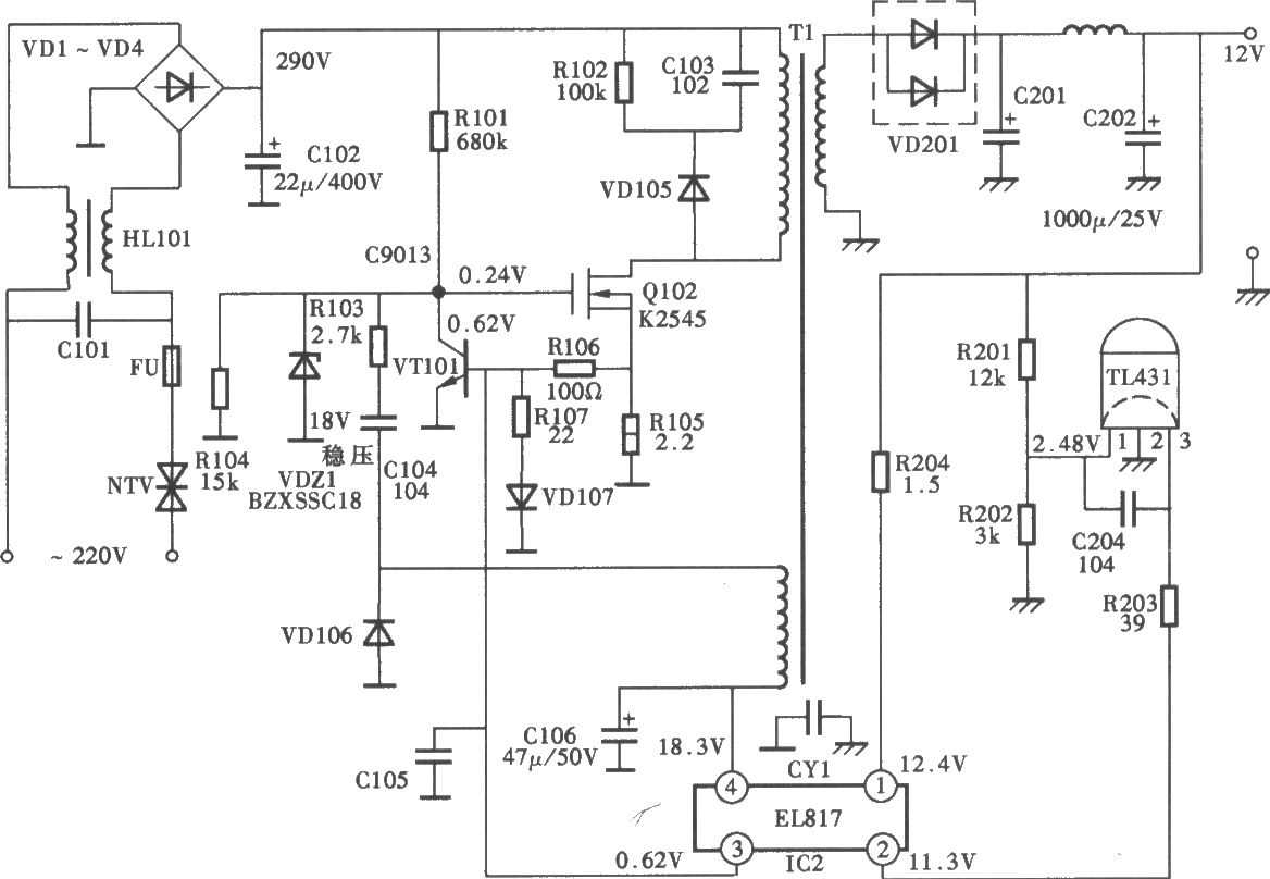
The PC817 optocoupler finds extensive application in various electronic systems and devices, including but not limited to:
- Isolated Power Supplies: It is commonly used to provide isolation in power supply circuits, protecting sensitive components from high voltages or transients.
- Microcontroller Interfacing: The PC817 allows safe interfacing between microcontrollers and high-power devices by providing isolation and voltage level shifting.
- Industrial Control Systems: It is employed in industrial automation, motor control, and measurement circuits to ensure accurate signal transmission and protect control equipment.
- Audio and Signal Transmission: The PC817 can be utilized in audio amplifiers, data transmission systems, and telecommunications equipment to overcome noise interference and improve signal integrity.
In conclusion, the PC817 optocoupler serves as an essential component in electronic systems, ensuring electrical isolation, facilitating signal transmission, and enhancing system performance and safety. Its versatility and wide range of applications make it a fundamental building block in various industries.
Important Parameters and Specifications in the Optocoupler PC817 Datasheet
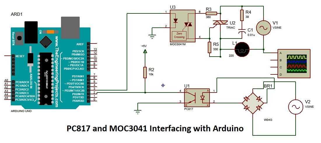
In the documentation for the PC817 optocoupler, there are several essential parameters and specifications that play a crucial role in understanding the device’s capabilities and limitations. Familiarizing oneself with these key aspects is vital for anyone working with the PC817, ensuring its optimal usage and performance.
One of the fundamental parameters to consider is the PC817’s input current transfer ratio (CTR). This ratio represents the relationship between the input forward current and the output collector current. A higher CTR indicates better efficiency in transferring input signals to the output side, while a lower CTR may result in signal loss or distortion.
Another critical specification is the PC817’s isolation voltage, which measures the level of electrical isolation between the input and output sides of the device. It is important to understand that the PC817 is designed to provide galvanic isolation, protecting sensitive circuitry from potential voltage surges or noise. Therefore, a higher isolation voltage rating ensures enhanced insulation capabilities.
The PC817 datasheet also includes information regarding the device’s maximum forward diode current and reverse voltage, denoted as IF and VR, respectively. These limits determine the maximum safe current and voltage levels that can be applied to the input side of the optocoupler without risking damage or malfunction. Operating within these specified limits is crucial for the device’s longevity and reliable operation.
Furthermore, the PC817 datasheet provides details about the device’s response time, which refers to the speed at which the optocoupler can transfer signals from the input to the output side. A shorter response time allows for faster data transfer, making the PC817 suitable for applications that require swift signal transmission.
| Parameter | Description |
|---|---|
| Input Current Transfer Ratio (CTR) | Indicates the efficiency of signal transfer from the input to the output side |
| Isolation Voltage | Measures the level of electrical isolation between the input and output sides |
| Maximum Forward Diode Current (IF) | Determines the maximum safe current that can be applied to the input side |
| Reverse Voltage (VR) | Specifies the maximum safe voltage that can be applied to the input side |
| Response Time | Indicates the speed at which signals are transferred from input to output |
It is crucial to thoroughly analyze the PC817 datasheet to understand these parameters and specifications fully. Doing so will enable engineers and designers to make informed decisions when incorporating the PC817 optocoupler into their applications, ensuring optimal performance and reliability.
How to Read and Interpret the Optocoupler PC817 Datasheet
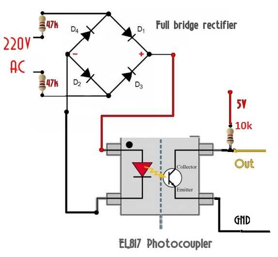
When working with the Optocoupler PC817, it is essential to have a thorough understanding of its datasheet in order to fully leverage its capabilities. The datasheet contains valuable information that can help in selecting and implementing the optocoupler in various electronic circuits. This section will guide you on how to effectively read and interpret the PC817 datasheet, enabling you to make informed decisions.
Understanding the Device Specifications
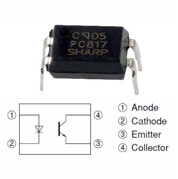
To comprehend the PC817 datasheet, it is important to familiarize yourself with the device specifications. These specifications provide detailed information about the optocoupler’s electrical and mechanical characteristics. Key specifications include input current, output voltage, isolation voltage, and operating temperature range. By carefully studying these specifications, you can determine whether the optocoupler is suitable for your application and its limitations.
Interpreting the Electrical Characteristics
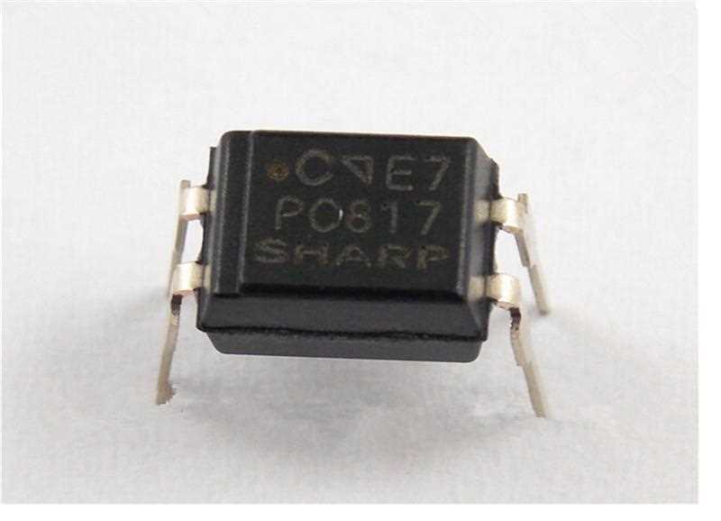
The electrical characteristics section of the datasheet provides crucial information about the PC817’s performance in various operating conditions. It includes parameters such as forward voltage, collector-emitter current transfer ratio, and input-output capacitance. Understanding these characteristics will help you evaluate the optocoupler’s electrical behavior, such as its efficiency, response time, and signal transmission capabilities.
One important characteristic to consider is the PC817’s CTR (Current Transfer Ratio). This ratio represents the amplification of input current at the LED side to the output current at the phototransistor side. By analyzing the CTR curve provided in the datasheet, you can determine the optocoupler’s linearity, saturation level, and the optimal input current required for your specific application.
Examining the Application Circuits
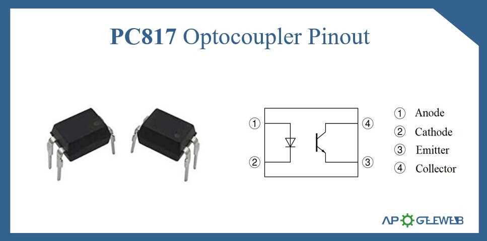
The datasheet of the PC817 often includes typical application circuits that showcase how the optocoupler can be utilized in practical scenarios. These circuits serve as a reference guide for designing and implementing the optocoupler in different applications, such as motor control, signal isolation, and switching power supplies. Studying these circuits can provide valuable insights into the optimal configuration and component selection, saving time and effort in the design process.
| Key Points to Consider: |
|---|
| – Familiarize yourself with the device specifications |
| – Analyze the electrical characteristics and CTR |
| – Study the application circuits for reference |
By investing time in reading and interpreting the PC817 datasheet, you can gain a comprehensive understanding of the optocoupler’s capabilities and limitations. This knowledge will enable you to make informed decisions during the selection and implementation process, ensuring optimal performance and reliability in your electronic circuits.