In the world of electronic devices, there exists a component that plays a vital role in amplification and control circuits – the BD140. This versatile device possesses unique characteristics that make it an indispensable part of countless applications in the realm of electronics. Let us dive deeper into the fascinating world of BD140 and unravel the features that set it apart from its counterparts.
Imagine a small component that possesses the power to control the flow of electric current effortlessly. Enter the BD140, a dynamic through-hole transistor that exhibits exemplary performance in a range of circuits. This component is known for its ability to amplify signals and regulate current with precision, making it an indispensable choice for engineers and hobbyists alike.
One of the standout features of the BD140 is its versatility. It seamlessly adapts to various operating conditions and can withstand high voltage levels, making it a dependable choice for numerous applications. Whether it is audio amplification, motor control systems, or voltage regulation circuits, the BD140 proves its mettle by delivering exceptional performance consistently.
Furthermore, the BD140 boasts a robust design that ensures its longevity and reliability. With its heat sink capabilities and thermal protection features, this component can handle high temperatures without compromising its performance. This makes it an ideal choice for devices that require continuous and prolonged operation, assuring engineers of its resilience and durability.
In conclusion, the BD140 is a powerful component that boasts outstanding attributes and immense potential in the realm of electronics. Its ability to amplify signals, regulate current, and withstand high voltage levels sets it apart from its counterparts. With its versatility and robust design, the BD140 proves to be a reliable choice for various electronic applications. As we delve further into the intricacies of this remarkable component, we begin to appreciate its significance and the value it brings to the world of technology and innovation.
An Overview of the BD140 Datasheet
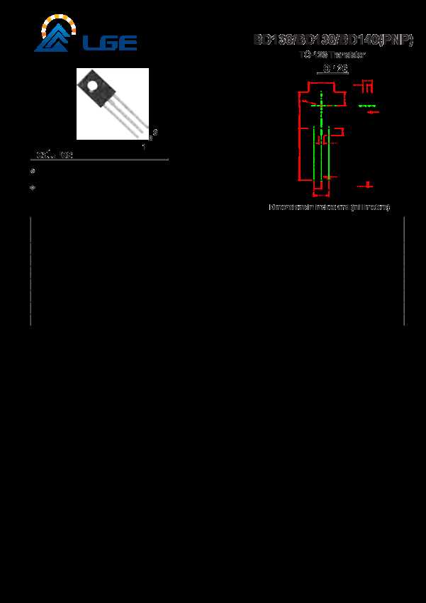
In this section, we will provide a comprehensive overview of the BD140 datasheet, a document that contains crucial technical information about the BD140 transistor. This overview aims to give you a clear understanding of the key aspects covered in the datasheet, allowing you to make informed decisions and utilize the BD140 transistor effectively in your electronic projects.
Data Specifications
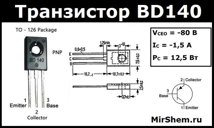
One of the essential components of the BD140 datasheet is the data specifications section, where you can find detailed information about the electrical and thermal characteristics of the transistor. This section includes parameters such as maximum ratings, DC current gain, collector-emitter saturation voltage, and power dissipation. By studying these specifications, you can determine the transistor’s capabilities and limitations, ensuring proper usage and design considerations.
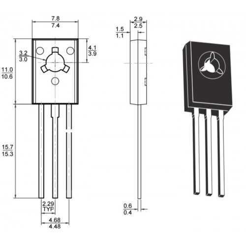
Another crucial part of the BD140 datasheet is the package information section. This section provides details about the transistor’s physical characteristics, including its package type, dimensions, pin configuration, and recommended soldering techniques. Understanding this information is essential when integrating the BD140 transistor into your circuit design or when selecting an appropriate package for your application needs.
Application Notes and Circuit Examples
Additionally, the BD140 datasheet includes application notes and circuit examples that demonstrate how to use the transistor effectively in various electronic applications. These valuable resources provide insights into the transistor’s practical applications, allowing you to optimize its performance and ensure reliable operation in your specific circuit configurations. Whether you are designing amplifiers, switching circuits, or voltage regulators, these application notes can be a valuable reference.
- Data specifications: Provides detailed electrical and thermal characteristics of the transistor.
- Package information: Gives physical details and pin configuration of the transistor package.
- Application notes and circuit examples: Demonstrate practical usage and circuit design considerations for the BD140 transistor.
By understanding the contents of the BD140 datasheet and utilizing the information provided, you can confidently incorporate the transistor into your electronic projects, harnessing its capabilities to achieve desired results and overall success in your designs.
The Key Specifications of the BD140 Transistor
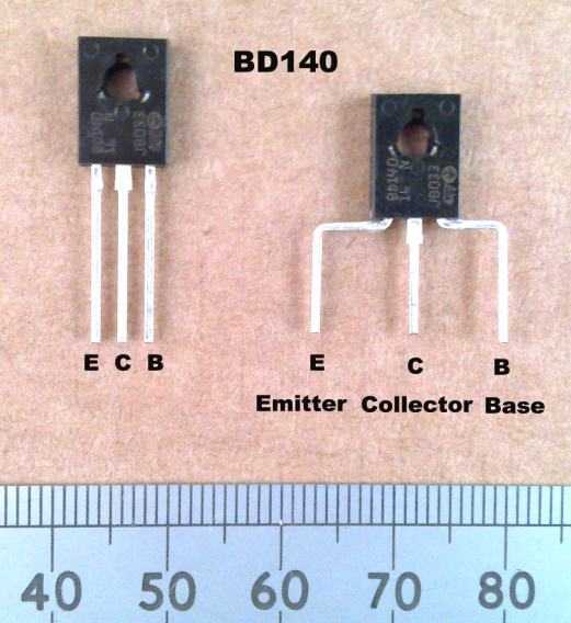
When it comes to the BD140 transistor, understanding its key specifications is crucial for anyone working in the field of electronics. By delving into the technical details and performance characteristics, we can gain a comprehensive understanding of this versatile component and its potential applications.
1. Power Dissipation
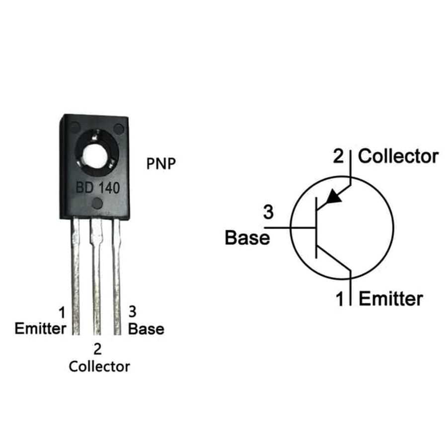
One of the primary aspects to consider is the power dissipation of the BD140 transistor. This refers to the maximum amount of power that the device can handle without risking damage or failure. It is an important parameter to take into account when designing circuits that involve power distribution.
2. Collector Current
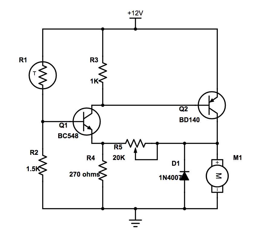
The collector current, another crucial specification, determines the maximum current that the transistor can handle through its collector terminal. It indicates the capability of the BD140 to handle various levels of current flow, ensuring stable and reliable performance in different circuit applications.
Moreover, other important specifications that should be considered include the gain, voltage ratings, and switching characteristics. These specifications play a critical role in determining the overall performance and limitations of the BD140 transistor.
By carefully examining and understanding the key specifications of the BD140 transistor, engineers and enthusiasts can make informed decisions about incorporating this component into their designs, enabling them to harness its capabilities effectively and achieve optimal circuit performance.
Understanding the Pin Configuration of the BD140
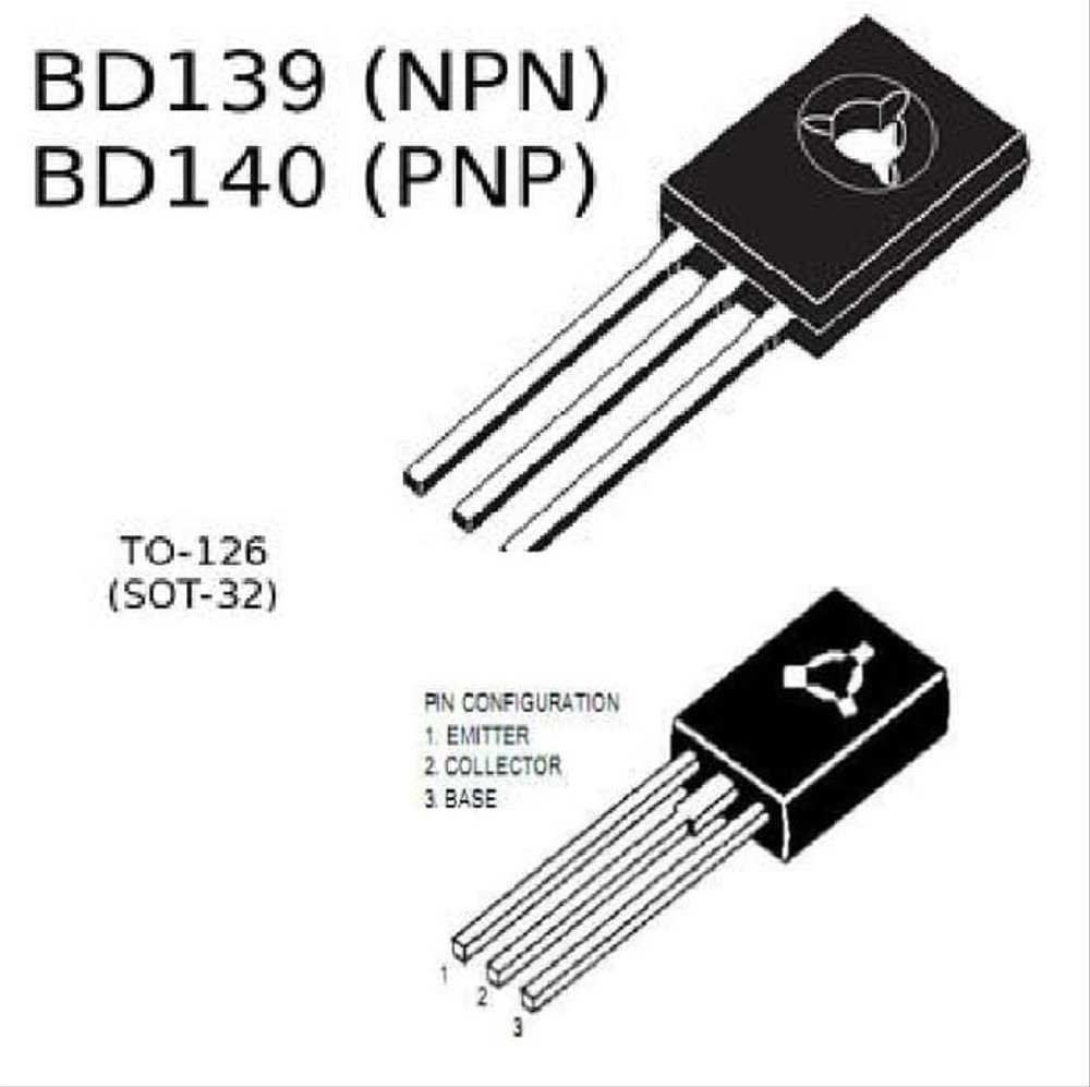
In this section, we will delve into the intricacies of the pin configuration of the BD140 transistor. By comprehending the various pins of this component, you will be able to grasp its functionality and how it can be effectively integrated into electronic circuits.
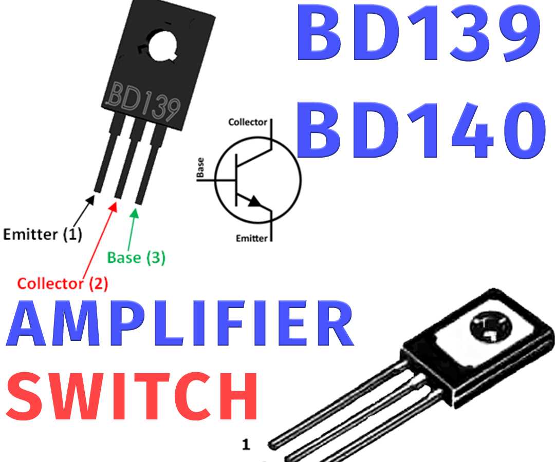
The BD140 transistor features three pins, namely the collector (C), base (B), and emitter (E). Each of these pins plays a crucial role in the operation of the transistor, enabling it to amplify and control the flow of current.
The collector (C) pin serves as the output terminal of the transistor, where the amplified signal is collected. It is typically connected to the power supply or the load in a circuit, playing a vital role in ensuring the correct function and performance of the transistor.
The base (B) pin acts as the control terminal of the transistor. By applying a small current or voltage to this pin, we can control the larger current flowing between the collector and the emitter. This control enables the transistor to function as an amplifier or a switch, depending on the circuit configuration.
The emitter (E) pin functions as the input terminal of the transistor. It is responsible for supplying the input current or voltage that controls the operation of the transistor. The emitter is typically connected to the ground or a reference point in the circuit, offering stability and proper biasing.
To better visualize the pin configuration, refer to the table below:
| Pin | Description |
|---|---|
| C (Collector) | Output terminal where the amplified signal is collected |
| B (Base) | Control terminal for regulating the flow of current |
| E (Emitter) | Input terminal responsible for supplying the controlling current |
Understanding the pin configuration of the BD140 transistor is fundamental for circuit designers and electronics enthusiasts. By analyzing the roles of each pin, you can harness the full potential of this component and utilize it effectively in your electronic projects.