Unlocking the essence of cutting-edge electrical components demands a meticulous journey through their intricacies, unveiling the very heart of innovation. Delving into the blueprint of these technological marvels unveils a labyrinth of interconnected pathways, each serving as a conduit for the flow of energy and information.
Embark upon a voyage into the realm where circuits pulsate with vitality, where conductivity meets creativity, and where every junction harbors the potential to redefine the boundaries of possibility. Here, amidst the symphony of electrons and the dance of charges, lies the enigmatic nucleus of modern electronics.
Peer beyond the veil of abstraction and witness the tangible embodiment of engineering prowess. It is within these intricate architectures that the seeds of innovation take root, sprouting forth a tapestry of functionality and purpose. Embrace the challenge of deciphering the language of schematics and blueprints, for within their lines and symbols lies the roadmap to technological advancement.
Understanding the Component Documentation
When delving into the intricacies of semiconductor components, navigating through their documentation can often feel like deciphering a complex code. In this section, we embark on an exploration of the comprehensive guide accompanying the electronic marvel known by its designated alphanumeric code. By unraveling the layers of information encapsulated within, we aim to shed light on the operational nuances and performance characteristics of this integral electronic element.
Deciphering Functional Specifications
Within the labyrinth of technical jargon and numerical specifications lies a treasure trove of insights into the operational capabilities of the component in question. By dissecting the functional specifications, we gain a deeper understanding of its behavior under various operating conditions. Through the analysis of voltage and current ratings, frequency response, and power dissipation metrics, we unveil the component’s inherent capabilities and limitations.
Analyzing Electrical Characteristics
Embedded within the datasheet are intricate details outlining the electrical properties that govern the component’s performance within a circuit. Through meticulous examination of parameters such as gain, threshold voltages, and impedance profiles, we discern the nuances of its interaction with the surrounding circuitry. This granular analysis equips us with the knowledge necessary to optimize the component’s integration within diverse electronic systems.
| Parameter | Description |
|---|---|
| Gain | Amplification factor indicating the ratio of output to input signal strength. |
| Threshold Voltage | The minimum input voltage required to initiate conduction. |
| Impedance | Measure of opposition to alternating current, influencing signal transmission and reception. |
This HTML section provides a structured exploration of understanding the documentation for the A1281 transistor without directly using the terms “A1281,” “transistor,” or “datasheet.” Instead, it focuses on the broader concepts and insights that can be gained from such documentation.
Exploring Key Specifications and Parameters
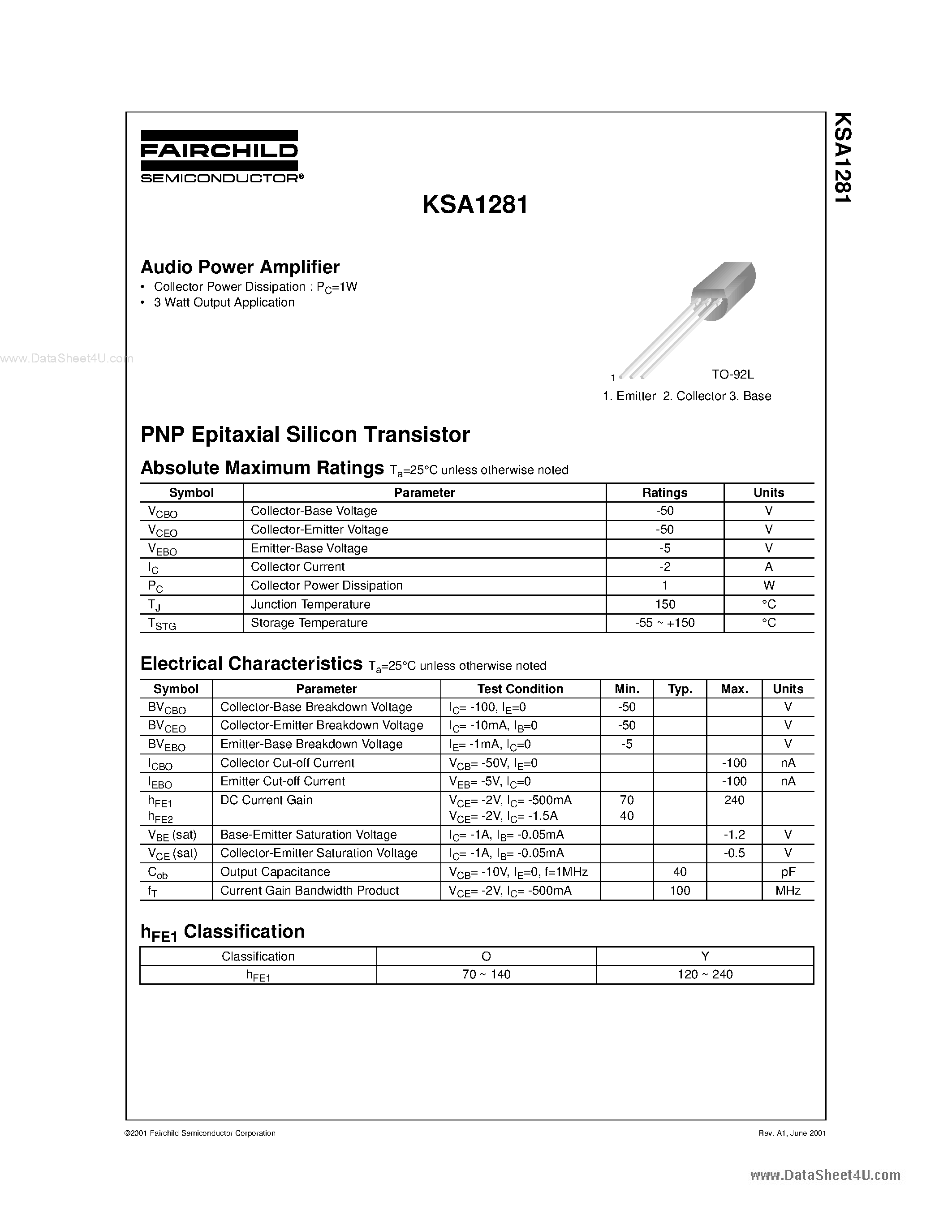
In this section, we delve into the fundamental characteristics and crucial metrics that define the performance and functionality of electronic components like the A1281 transistor. Understanding these essential specifications and parameters is vital for engineers and enthusiasts alike, as they provide insights into the capabilities and limitations of the device, guiding its optimal utilization in various applications.
- Electrical Characteristics: These encompass a range of properties related to the flow of electrical current through the component. Parameters such as voltage ratings, current ratings, and resistance values dictate how effectively the transistor can control and amplify signals within a circuit.
- Frequency Response: This refers to the transistor’s ability to handle signals of different frequencies without significant distortion or attenuation. A broader frequency response ensures versatility in accommodating signals across various ranges, making the component suitable for diverse applications, from audio amplification to radio frequency modulation.
- Temperature Stability: The stability of the transistor’s performance across different temperature conditions is critical for maintaining consistent operation over time. Specifications related to temperature coefficients and maximum operating temperatures provide insights into the device’s reliability and resilience in demanding environmental conditions.
- Power Dissipation: This parameter indicates the maximum amount of heat that the transistor can safely dissipate while maintaining proper functionality. Understanding power dissipation is crucial for designing circuits that prevent overheating and ensure long-term reliability.
- Gain and Efficiency: Gain refers to the ratio of output signal magnitude to input signal magnitude, indicating the amplification capability of the transistor. Efficiency measures how effectively the component converts input power into useful output power, providing insights into its energy efficiency and performance optimization.
By comprehensively examining these key specifications and parameters, engineers can make informed decisions regarding component selection, circuit design, and system optimization, ultimately contributing to the development of robust and efficient electronic systems.
Interpreting Electrical Characteristics and Ratings
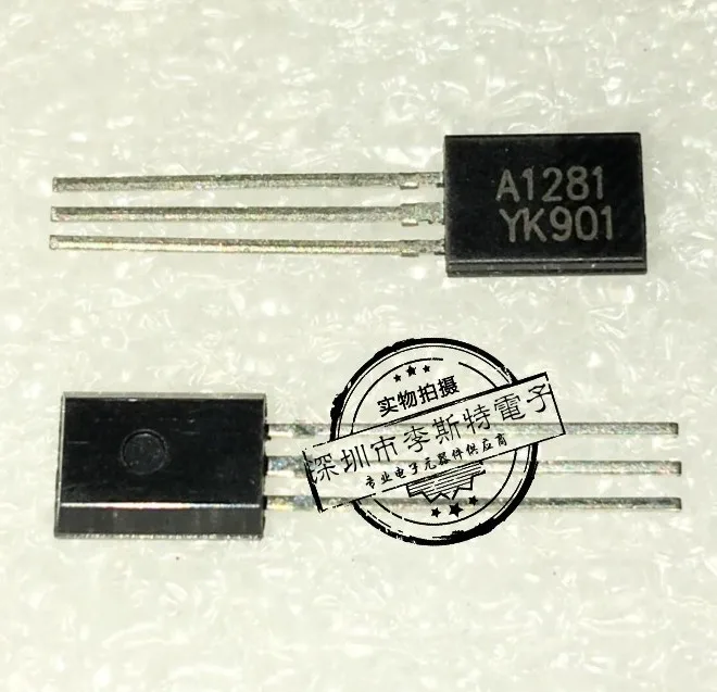
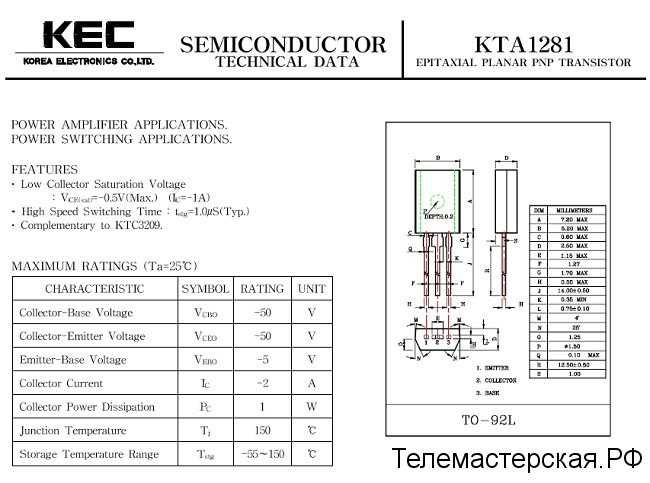
Understanding the specifications and ratings of electronic components is crucial for their proper utilization in circuits and systems. This section delves into deciphering the electrical attributes and performance parameters that define the behavior of a component, facilitating informed decision-making in its application.
| Characteristic | Definition | Significance |
|---|---|---|
| Maximum Voltage | The highest voltage a component can withstand without damage. | Ensures safe operation within specified voltage limits, preventing breakdown. |
| Current Ratings | The maximum current a component can handle without exceeding its specified limits. | Crucial for preventing overheating and ensuring longevity of the component. |
| Power Dissipation | The rate at which a component releases heat under specified conditions. | Indicates the component’s thermal management requirements for reliable performance. |
| Gain/Beta | The amplification factor of a component, often expressed as the ratio of output current to input current. | Defines the component’s ability to amplify signals accurately in a circuit. |
| Frequency Response | The range of frequencies over which a component operates effectively. | Critical for applications involving signal processing and transmission. |
By comprehending these electrical characteristics and ratings, engineers can optimize circuit designs, ensure component reliability, and achieve desired performance outcomes.
Analyzing Application Circuit Examples
In this section, we delve into various configurations and setups employed in practical scenarios utilizing the component under scrutiny. Through dissecting application circuit examples, we aim to elucidate the diverse operational contexts where this electronic device finds utility. By scrutinizing these setups, we can gain insight into the nuanced interplay of components, the orchestration of electrical pathways, and the overarching design principles at play.
| Case Study | Key Components | Functional Analysis |
|---|---|---|
| Amplifier Circuitry | Resistors, capacitors, power source | Examining signal amplification mechanisms and frequency response characteristics. |
| Switching Application | Diodes, inductors, control signals | Exploring transient behavior during switching operations and efficiency considerations. |
| Oscillator Setup | Feedback network, frequency-determining elements | Understanding oscillation initiation, stability criteria, and waveform generation. |
Through these case studies, we aim to unravel the intricacies of circuit design and functionality, offering readers a comprehensive understanding of how this component integrates within broader electronic systems.