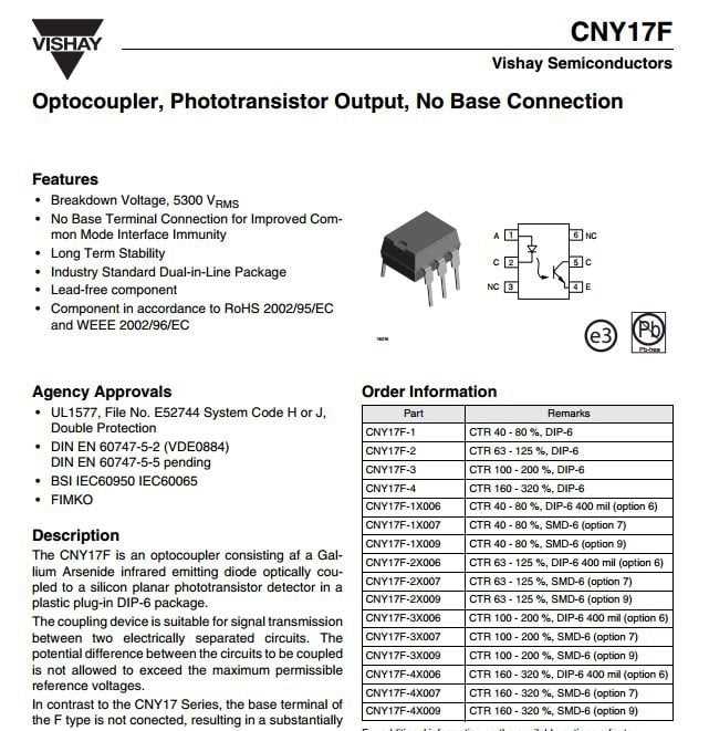
Embark on a journey into the realm of electronic communication, where light bridges the gap between isolation and connection.
Within the labyrinth of electronic components lies a discreet yet indispensable element, often overlooked amidst the complexities of circuitry. This enigmatic entity, known by its alphanumeric cryptonym Cny17f 3, operates as a silent sentinel, guarding the delicate boundaries between circuits with its optical prowess.
Delve into the intricacies of its design and functionality, uncovering the subtle nuances that define its role in the grand symphony of electrical engineering.
Through a lens of exploration, we decipher the cryptic language of its datasheet, unraveling the mysteries concealed within its intricate diagrams and technical specifications.
Join us as we illuminate the path to understanding, shedding light on the significance of this optical enabler in the vast expanse of electronic innovation.
Understanding the Cny17f 3 Optocoupler Specifications
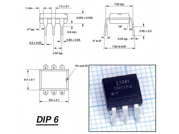
Delving into the intricacies of the documentation surrounding the Cny17f 3 optocoupler unveils a wealth of insights crucial for its optimal utilization. This section aims to navigate through the labyrinthine details encapsulated within the datasheet, shedding light on the operational nuances and performance characteristics.
Deciphering Functional Attributes
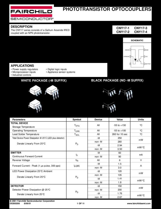
Exploring the functionality and operational parameters of this component unveils its inherent capabilities and limitations. By dissecting the specifications with precision, one can glean valuable information pertaining to its voltage, current, and frequency handling capacities.
Interpreting Application Guidelines
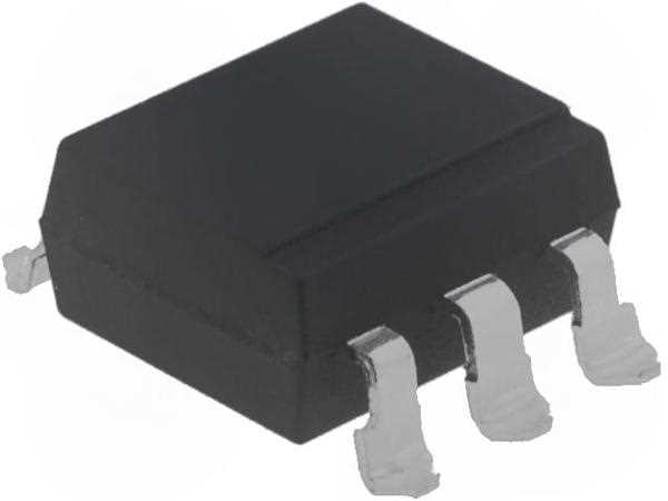
Furthermore, comprehending the guidelines outlined within the datasheet facilitates the seamless integration of the Cny17f 3 into diverse circuitry configurations. Insights into recommended usage scenarios, isolation techniques, and environmental considerations empower engineers to harness its potential effectively.
In essence, a comprehensive understanding of the Cny17f 3 optocoupler datasheet transcends mere scrutiny of technical jargon; it serves as a roadmap towards unlocking its full functionality and optimizing its performance within myriad electronic applications.
Key Specifications Explained
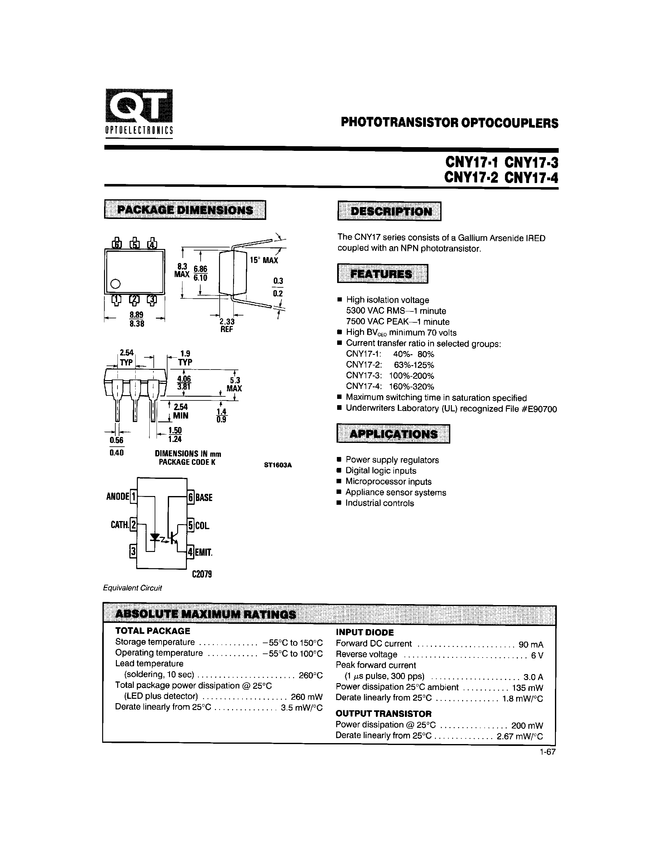
Understanding the fundamental parameters of a component is crucial for assessing its performance and compatibility within a circuit. In this section, we delve into the essential characteristics of the mentioned device, shedding light on its operational capabilities and limitations.
Input-Output Isolation
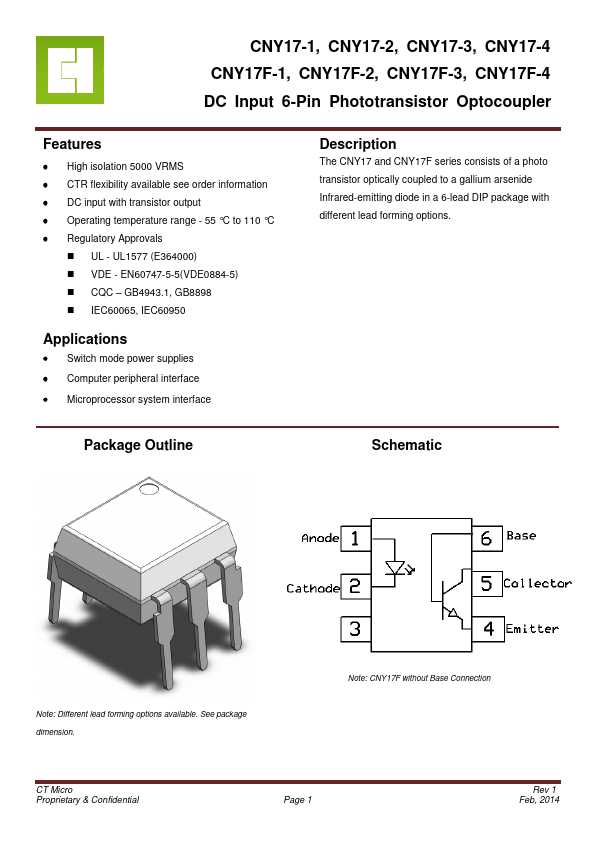
One of the primary aspects to consider is the degree of isolation between the input and output sections of the optocoupler. This specification indicates the device’s ability to transmit signals across a barrier without direct electrical connection, ensuring safety and preventing potential interference between connected systems.
Maximum Input Voltage
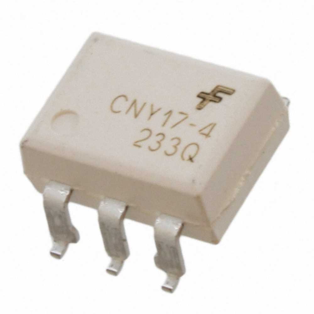
The maximum input voltage delineates the threshold beyond which the optocoupler may malfunction or sustain damage. It defines the upper limit of voltage that the input LED can withstand without compromising its performance or longevity. Understanding this parameter is crucial for designing circuits that operate within safe voltage ranges.
Application Circuit Design Tips
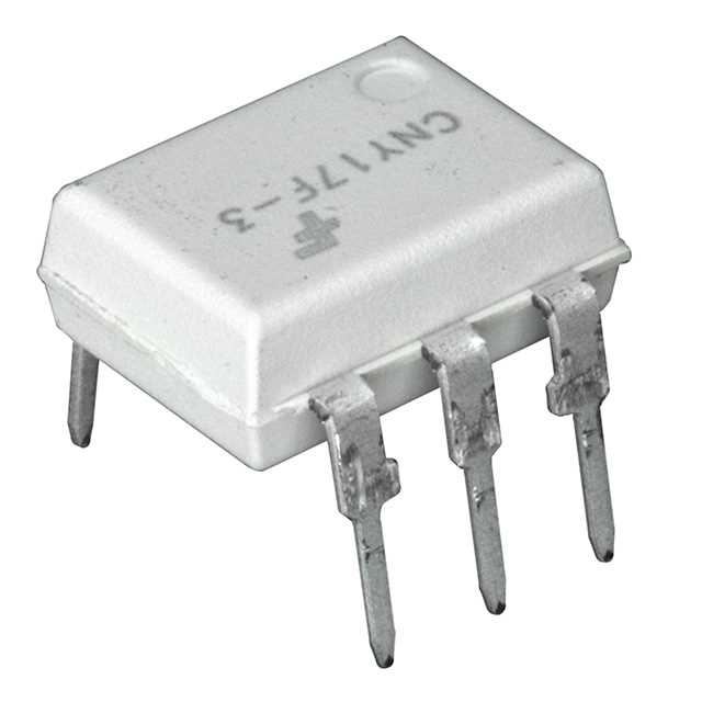
When integrating optical isolators into your circuitry, it’s crucial to pay close attention to the design aspects that can significantly influence overall performance. This section provides essential insights into optimizing your application circuit for reliable operation and enhanced functionality.
Firstly, focus on establishing robust electrical isolation between input and output sections to prevent signal interference and ensure safety. Implementing proper isolation techniques helps maintain signal integrity and minimizes the risk of electrical hazards in your system.
Furthermore, consider the selection of appropriate peripheral components to complement the optocoupler’s functionality effectively. Optimize resistor values, capacitor configurations, and other supporting elements to achieve desired performance metrics such as response time and noise immunity.
Additionally, pay attention to layout considerations to minimize parasitic effects and maintain signal integrity throughout the circuit. Proper component placement and routing techniques can mitigate issues such as cross-talk and electromagnetic interference, enhancing overall reliability.
Moreover, thermal management plays a crucial role in ensuring the long-term stability and performance of your application circuit. Adequate heat sinking and thermal dissipation measures help prevent temperature-induced degradation and ensure consistent operation under varying environmental conditions.
Lastly, thorough testing and validation are indispensable steps in the design process. Conduct comprehensive functional tests and performance evaluations to verify the integrity and efficiency of your application circuit under real-world conditions. Iterative refinement based on test results can lead to further optimization and improved overall performance.
Troubleshooting and Common Issues
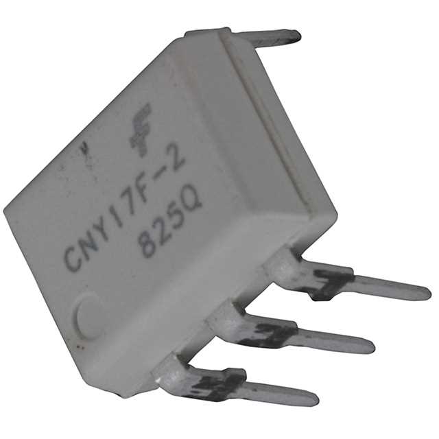
In this section, we’ll address common challenges and concerns that may arise when working with components similar to the Cny17f 3 optocoupler. Whether you’re encountering connectivity problems, signal distortion, or performance inconsistencies, we’ll provide insights and solutions to help you navigate through these obstacles effectively.
| Issue | Description | Solution |
|---|---|---|
| Interference | Signal disruptions caused by external electromagnetic fields or nearby electronic devices. | Isolate the circuit from sources of interference, shield sensitive components, or use filters to minimize signal distortion. |
| Component Failure | Unexpected malfunction or breakdown of the optocoupler or associated components. | Inspect for physical damage, ensure proper voltage and current levels, and replace faulty components as necessary. |
| Compatibility Issues | Incompatibility between the optocoupler and connected devices or systems. | Verify compatibility specifications, such as voltage and current requirements, and adjust connections or components accordingly. |
| Noise and Distortion | Introduction of unwanted noise or distortion in the transmitted signal. | Implement filtering techniques, improve grounding, or adjust signal amplification to minimize noise and distortion. |
| Temperature Sensitivity | Performance variations due to fluctuations in temperature. | Ensure proper thermal management, select components rated for the operating temperature range, or implement temperature compensation techniques. |
By addressing these common issues systematically and implementing appropriate solutions, you can enhance the reliability and performance of your optocoupler-based circuits, ensuring smooth operation in various applications.