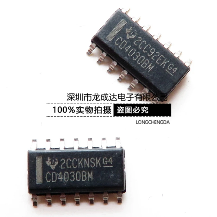
Technology continues to advance at an unprecedented pace, giving rise to a wide range of electronic devices that have become an integral part of our daily lives. At the heart of many of these devices lies a small yet powerful component known as the CD4030 integrated circuit. This versatile semiconductor, with its plethora of applications, has revolutionized the field of electronics.
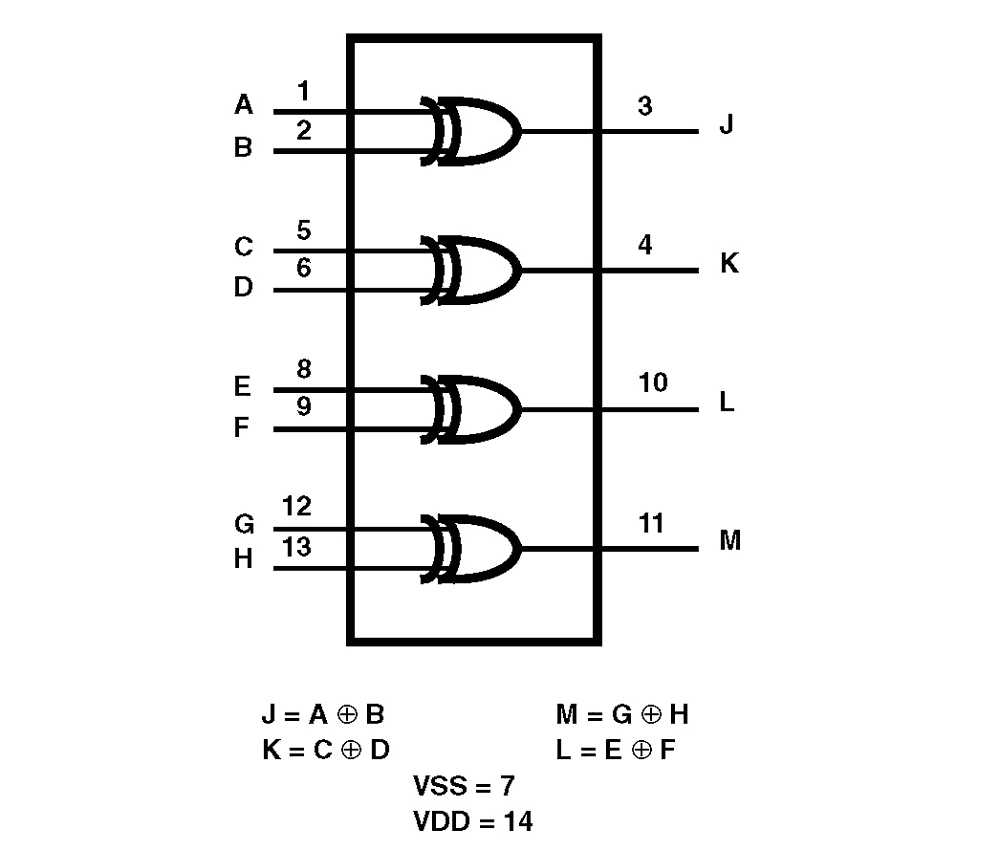
The CD4030, also referred to as a quad Exclusive OR (XOR) gate, functions as a logic gate and plays a crucial role in digital electronic circuits. Its primary function is to perform exclusive OR operations, allowing for the comparison of two binary values. This gate can process multiple input signals and produce a single output based on its logical operation.
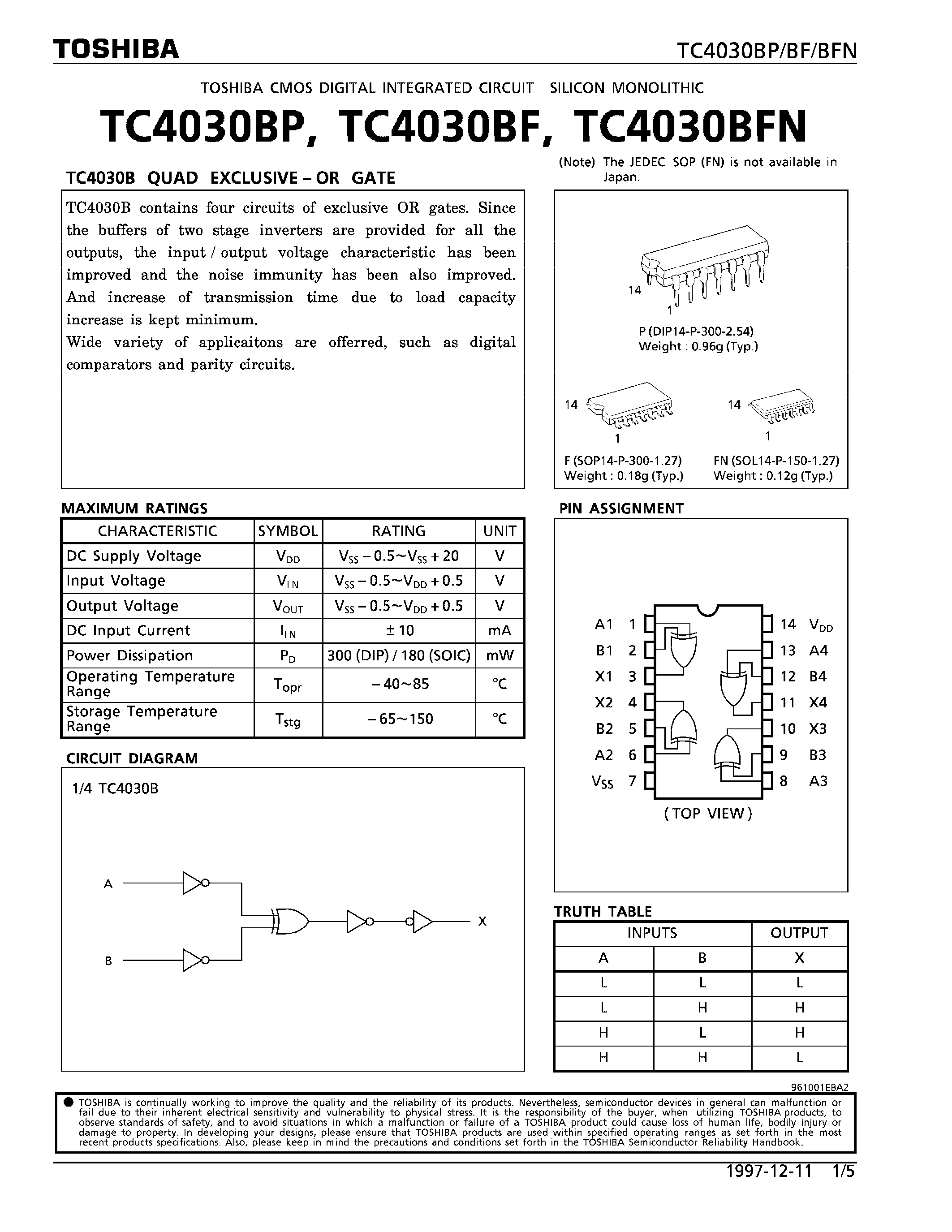
With its compact size and commendable performance, the CD4030 has become a staple in various electronic devices such as computers, smartphones, and even home appliances. Its ability to handle high-speed data processing and offer reliable output makes it an essential component in the ever-evolving world of electronics. Understanding the CD4030’s datasheet is vital for engineers and hobbyists alike, as it provides detailed technical specifications and guidelines for its proper utilization.
Discover the features and applications of the CD4030 IC
Explore the versatility and capabilities of the CD4030 integrated circuit (IC) as we delve into its unique features and wide range of applications. This electronic component offers a plethora of potentials, making it an essential tool for various electronic systems.
Enhanced Performance and Efficiency
The CD4030 IC boasts high-speed performance, allowing for efficient and accurate data processing. Its advanced technology enables seamless integration into different electronic designs, ensuring optimal functionality and reliable operation. With its low power consumption, the CD4030 IC can contribute to energy-efficient systems, making it an eco-friendly choice for electronics manufacturers.
Application Across Multiple Industries
The CD4030 IC finds applications in various industries, ranging from telecommunications and automotive to consumer electronics and aerospace. Its ability to perform logical operations, such as exclusive OR (XOR), makes it suitable for digital circuits and data processing systems. Furthermore, its compact size and compatibility with different voltage levels make it an ideal choice for space-constrained applications.
Whether used in communication devices for signal processing or in automotive systems for control and monitoring, the CD4030 IC provides reliable performance and versatile functionality. Its widespread use in diverse industries attests to its trustworthiness and adaptability.
Understanding the Pin Configuration of CD4030
In this section, we will explore the pin configuration of the CD4030 integrated circuit, a versatile and widely used device in electronic circuits. Familiarizing oneself with the pinout of the CD4030 is crucial for proper understanding and utilization of its functionalities in circuit design and implementation.
1. Pinout Overview
The CD4030 is comprised of a 14-pin package with different pins arranged strategically to facilitate specific connections and operations within the circuit. Each pin serves a unique purpose and plays a significant role in the overall functionality of the CD4030 integrated circuit.
Pinout assignment of the CD4030 may vary depending on the manufacturer, but the general pin configuration remains consistent. The diagram below illustrates the standard pinout arrangement of the CD4030 integrated circuit:
(Insert diagram here)
2. Pin Functions
Now, let’s delve into the detailed explanation of each pin’s function within the CD4030 integrated circuit:
- Pin 1: This pin serves as the input pin for the first XOR gate. It receives an input signal and compares it with the corresponding input from Pin 2.
- Pin 2: This pin also functions as an input pin for the first XOR gate. It receives an input signal and compares it with the corresponding input from Pin 1.
- Pin 3: This pin connects to the output of the first XOR gate and provides the result of the XOR operation.
- Pin 4: Acting as an input pin for the second XOR gate, this pin receives an input signal and compares it with the corresponding input from Pin 5.
- Pin 5: Similarly, this pin serves as an input pin for the second XOR gate. It receives an input signal and compares it with the corresponding input from Pin 4.
- Pin 6: This pin connects to the output of the second XOR gate and provides the result of the XOR operation.
- Pin 7: Functioning as an input pin for the third XOR gate, this pin receives an input signal and compares it with the corresponding input from Pin 8.
- Pin 8: This pin also acts as an input pin for the third XOR gate. It receives an input signal and compares it with the corresponding input from Pin 7.
- Pin 9: This pin connects to the output of the third XOR gate and provides the result of the XOR operation.
- Pins 10, 11, 12, and 13: These pins serve as power supply and ground connections, providing the necessary voltage and stability for the CD4030 integrated circuit.
- Pin 14: Also known as the VCC pin, this pin is the positive power supply terminal of the CD4030. It is usually connected to the positive power rail.
Understanding the pin configuration of the CD4030 is crucial for proper integration and utilization of this versatile integrated circuit in electronic circuits. By comprehending the functions and interconnections of each pin, engineers and hobbyists can effectively design and implement circuitry utilizing the CD4030, allowing for a wide range of possible electronic applications.
Learn how to connect and utilize the pins of the CD4030 IC
Discover the essential information regarding the proper connection and effective utilization of the various pins on the CD4030 Integrated Circuit (IC). By understanding the function and role of each pin, you can ensure correct functionality and optimize performance when working with the CD4030 IC.
To make the most of the CD4030 IC, it is crucial to understand how to connect it to external components and utilize its different pins. This knowledge allows you to tailor the IC’s behavior to meet your specific application requirements.
| Pin Number | Pin Name | Description |
|---|---|---|
| 1 | Input B | Input pin B for logical operations |
| 2 | Input A | Input pin A for logical operations |
| 3 | Output B | Output pin B for logical operations |
| 4 | Output C | Output pin C for logical operations |
| 5 | Input C | Input pin C for logical operations |
| 6 | Input D | Input pin D for logical operations |
| 7 | Output D | Output pin D for logical operations |
| 8 | VSS | Ground connection for the IC |
| 9 | Output A | Output pin A for logical operations |
| 10 | Power Supply (VDD) | Positive power supply connection for the IC |
By following the pin descriptions and understanding their functions, you can establish the necessary connections to external components and other ICs, enabling you to achieve the desired behavior from the CD4030 IC. This knowledge enhances your ability to design and implement circuits that leverage the full potential of the CD4030 IC.
Troubleshooting Tips for CD4030 Circuit Designs
When designing circuits using the CD4030 integrated circuit, it is important to understand the potential issues that may arise and have a systematic approach to troubleshooting them. This section provides some helpful tips to identify and resolve common problems encountered in CD4030 circuit designs.
1. Check Power Supply
One of the first steps in troubleshooting CD4030 circuit designs is to verify the power supply. Ensure that the voltage is within the specified range and stable. Fluctuations or incorrect voltage levels can lead to erratic behavior or complete failure of the circuit. Consider using a voltage regulator or stabilizer to maintain a consistent power supply.
2. Review Input Connections
Incorrect or loose connections of input signals can result in unexpected outputs or no response from the circuit. Double-check the wiring and connections to ensure they are accurate and secure. It is also important to verify that the input signals align with the logic levels expected by the CD4030, as improper levels can cause issues with the circuit’s functionality.
3. Verify Component Values
Make sure that the resistors, capacitors, and other components used in the CD4030 circuit are of the correct values specified in the design. Inaccurate component values can lead to incorrect timing, signal distortion, or improper functionality. Use a multimeter or other appropriate tools to measure and confirm the values of the components.
4. Check for Shorts and Opens

Shorts or open circuits can disrupt the flow of signals within the CD4030 circuit, causing unexpected behavior or complete failure. Inspect the circuit for any shorted or open connections, damaged traces, or soldering issues. Use appropriate test equipment, such as an ohmmeter, to identify and rectify these problems.
5. Examine the Output Stage

If the CD4030 circuit design involves driving external loads or other components, ensure that the output stage is properly configured. Check for issues such as insufficient current drive, incorrect output voltage levels, or improper load impedance matching. Consider using output buffering or impedance matching techniques to overcome these challenges.
By following these troubleshooting tips, designers can identify and address common issues encountered in CD4030 circuit designs. Remember to approach troubleshooting systematically, starting from the power supply and moving through various components and connections, until the problem is resolved. By ensuring a well-functioning circuit, the CD4030 can deliver reliable and efficient performance in various applications.
Explore common issues and solutions when working with CD4030-based circuits

When it comes to working with circuits based on the CD4030 integrated circuit, there are a few common issues that engineers and hobbyists may encounter. Understanding these challenges and their potential solutions is crucial for successful circuit design and troubleshooting. In this section, we will explore some of these common issues and offer practical solutions to overcome them.
1. Voltage Supply Problems
One of the most common issues when working with CD4030-based circuits is related to voltage supply. It is essential to ensure that the input voltage provided to the CD4030 is within its specified operating range, typically 3-15V. Deviating from this voltage range can result in improper circuit behavior and potential damage to the IC.
To address voltage supply problems, it is recommended to use a regulated power supply that can provide a stable voltage within the specified range. Additionally, verifying the voltage levels using a multimeter can help identify any inconsistencies or fluctuations that may be causing issues.
2. Signal Integrity Challenges
Another common issue encountered when working with CD4030-based circuits is signal integrity. The CD4030 is sensitive to noise and can be affected by electromagnetic interference (EMI) or crosstalk from neighboring components or traces.
To improve signal integrity, it is crucial to minimize the length of signal traces and keep them away from potential noise sources. Ground planes or power planes can also be employed to reduce signal noise and improve overall circuit performance. Additionally, using bypass capacitors near the power supply pins of the CD4030 can help suppress noise and maintain signal integrity.
By being aware of these common issues and their solutions, engineers and hobbyists can effectively tackle challenges when working with CD4030-based circuits. Proper voltage supply management and attention to signal integrity are essential for ensuring reliable and optimal performance of the circuit.