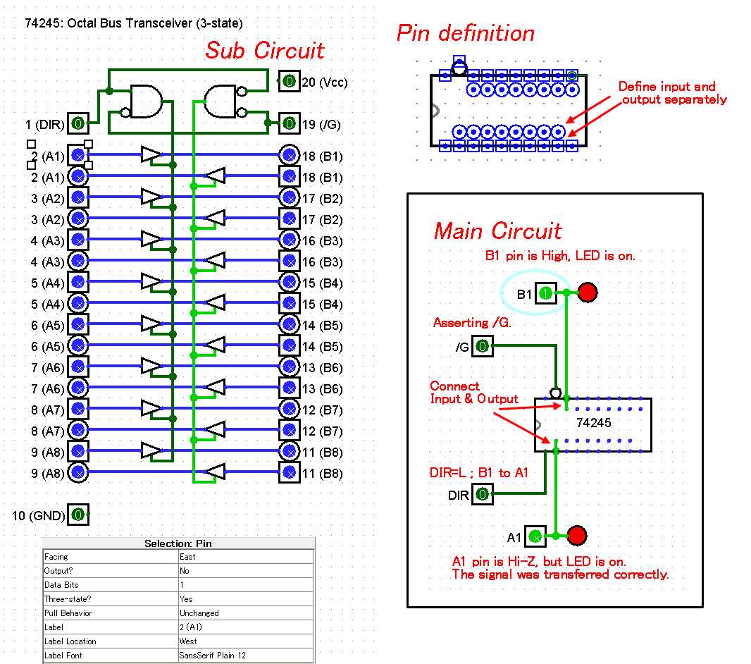
In the world of digital electronics, effective data transmission is of paramount importance. The seamless exchange of information between different components lies at the foundation of numerous technological advancements. And one vital element in this process is the integrated circuit (IC). Today, we will delve into the capabilities and functionalities of a highly versatile and widely used IC: the 74LS245.
The 74LS245, also known as the Octal Bus Transceiver, is a renowned integrated circuit that offers a range of features designed to facilitate smooth and efficient data transmission. With its ability to transmit eight bits of data bidirectionally, this IC acts as a bridge, connecting different parts of a digital system and allowing for seamless communication between them. Whether it’s transferring data from a microprocessor to memory or enabling communication between various devices, the 74LS245 plays a crucial role in maintaining the integrity of digital information.
One of the standout features of the 74LS245 is its compatibility with a wide range of voltage levels. With its ability to work with both TTL and CMOS logic levels, this IC offers flexibility and compatibility, making it suitable for integration into diverse electronic systems. Furthermore, the 74LS245 boasts a high output drive capability, ensuring reliable and fast data transmission. This robustness is especially crucial when dealing with large amounts of data or in applications that require quick response times.
Understanding the Functionality and Features of 74LS245
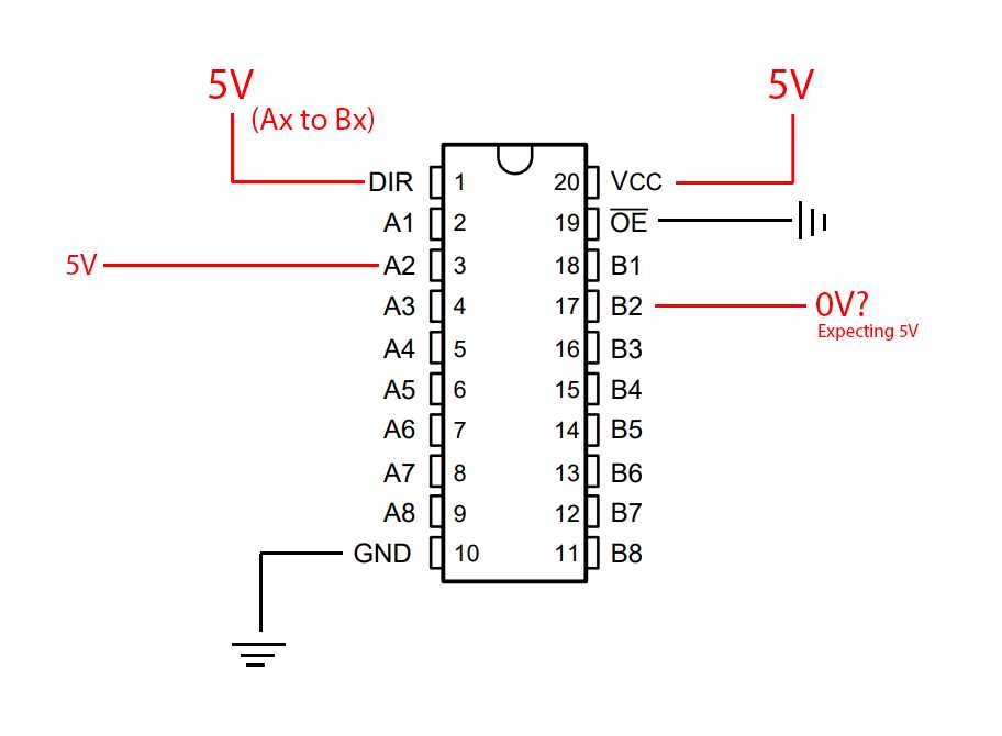
In this section, we will explore the inner workings and key aspects of the 74LS245 integrated circuit, delving into its functionality and the various features it offers. By gaining a comprehensive understanding of this component, you can effectively utilize it in your electronic design projects.
Overview of 74LS245
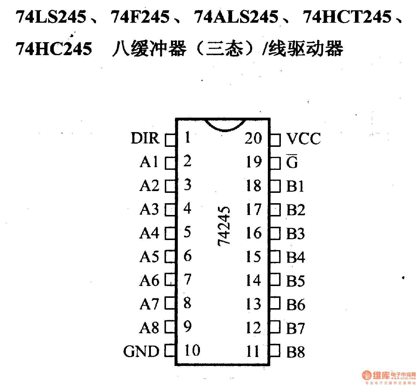
The 74LS245 is a widely used octal bus transceiver IC that facilitates bidirectional communication between two separate bus systems. It acts as a bridge, allowing seamless data transfer in both directions, making it ideal for interfacing between different logic families or microcontrollers.
Understanding the Functionality
This integrated circuit employs a tri-state logic, which effectively isolates the input and output lines when necessary. It features 8 bidirectional data lines, each with an input and output side. The direction of data flow is controlled by the direction control pin. When the direction is set to input, the IC allows data to flow from the external bus to the internal bus. Conversely, when the direction is set to output, the IC enables data transfer from the internal bus to the external bus.
The 74LS245 also incorporates a robust output buffer, which ensures minimal interference and impedance mismatch between different logic families. This buffer effectively amplifies the signals, providing reliable and stable output voltages for seamless data transmission.
Additionally, this integrated circuit features a high-speed design, enabling efficient data transfer at rapid rates. It is compatible with various standard logic families, making it versatile and widely used in a range of electronic applications.
It is important to note that the 74LS245 is a non-inverting bus transceiver, meaning that the logic levels on the input and output sides are the same. This characteristic simplifies its implementation, as there is no need for additional level shifting circuitry.
In summary, the 74LS245 offers bidirectional data transfer between separate bus systems, utilizing tri-state logic and a reliable output buffer. Its high-speed design and compatibility with various logic families make it a valuable component for efficient data transmission in electronic designs.
Working Principles and Applications of 74LS245
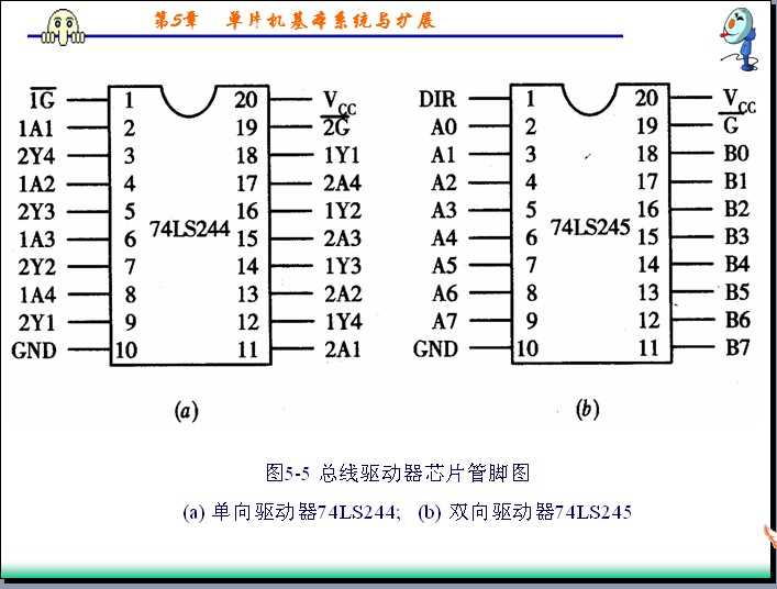
Understanding the Operational Principles of 74LS245
The 74LS245 is a versatile integrated circuit that plays a crucial role in data transmission and conversion. It operates on the principles of bidirectional voltage level shifting, allowing seamless communication between devices operating at different voltage levels. The chip acts as a buffer between the output and input lines, facilitating the transfer of data between systems.
Through its bidirectional capability, the 74LS245 can transmit data from a high-voltage system to a low-voltage system, or vice versa, without compromising signal integrity or causing voltage spikes that may damage the connected devices. The chip also incorporates tri-state outputs, enabling the control of data flow by enabling or disabling the outputs.
Applications of 74LS245
The 74LS245 finds widespread applications across various industries, thanks to its versatility and reliability. Some common applications include:
- Interfacing between microcontrollers and external devices with different voltage requirements
- Level shifting in data communication protocols such as I2C and SPI
- Data transfer between parallel and serial systems
- Buffering and signal conditioning in digital circuits
- Logic level conversion in mixed-voltage systems
By serving as a key component in these applications, the 74LS245 ensures efficient data exchange and compatibility between devices operating at different voltage levels. Its ability to handle bidirectional communication and tri-state outputs make it an essential tool in modern electronics.
Troubleshooting and Tips for Working with 74LS245
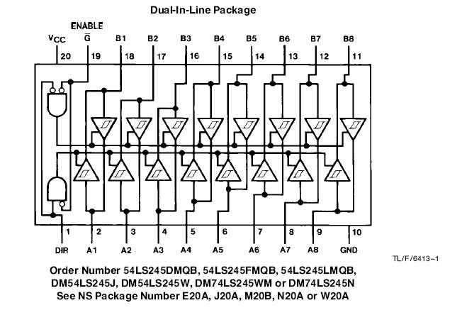
In this section, we will discuss various troubleshooting techniques and offer tips for working with the 74LS245 integrated circuit. The 74LS245 is a versatile and commonly used device in digital electronics projects, and understanding how to troubleshoot issues and optimize its performance can greatly enhance your project’s success. This section will provide valuable insights and strategies for troubleshooting common problems and offer helpful tips to ensure smooth operation and maximize the potential of the 74LS245 in your projects.
One important aspect to consider when working with the 74LS245 is ensuring proper power supply connections and voltage levels. Inadequate or unstable power supply can lead to unexpected behavior or even damage the circuit. It is crucial to double-check the power supply connections, ensure the correct voltage levels are being applied, and use appropriate decoupling capacitors to minimize noise and voltage fluctuations. Additionally, always refer to the datasheet for specific voltage requirements and recommended power supply configurations.
Another common issue when working with the 74LS245 is signal integrity and noise. As with any digital circuit, noise can cause signal distortion and introduce errors. To mitigate this, it is advisable to place decoupling capacitors near the power supply pins of the 74LS245 and ensure proper grounding techniques are used. Shielding sensitive signal lines from sources of electromagnetic interference can also help improve signal quality.
Furthermore, if you encounter unexpected behavior or malfunctioning of the 74LS245, it is essential to isolate and identify potential causes. Start by checking the connections and ensuring all inputs and outputs are correctly connected. Use a logic analyzer or oscilloscope to observe the signals at various points in the circuit and compare them with expected values. This can help in identifying signal integrity issues, incorrect wiring, or faulty components. Additionally, try replacing the 74LS245 with a known working unit to rule out any potential defects or damage to the IC itself.
Finally, it is beneficial to optimize the performance of the 74LS245 by understanding its timing characteristics and limitations. The datasheet provides valuable information on propagation delays, setup and hold times, and maximum operating frequencies. By adhering to these specifications and designing your circuit accordingly, you can ensure reliable operation and prevent timing-related issues.
| Troubleshooting Tip | Description |
|---|---|
| Ensure proper power supply | Check power supply connections and voltage levels to prevent circuit damage. |
| Minimize noise and signal distortion | Use decoupling capacitors, proper grounding, and shielding techniques to improve signal integrity. |
| Isolate and identify potential causes | Check connections, observe signals, and replace components to identify and resolve issues. |
| Optimize performance | Design circuits based on timing characteristics and limitations specified in the datasheet. |
By following these troubleshooting techniques and implementing the suggested tips, you can effectively address common issues and ensure successful operation when working with the 74LS245 integrated circuit. Remember to always refer to the datasheet for specific details and consult relevant resources for further assistance.