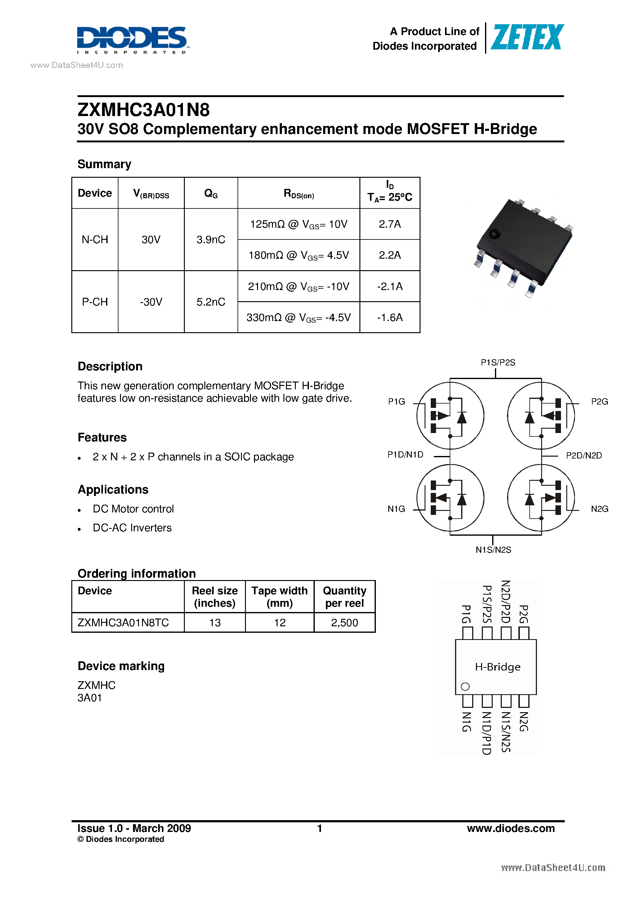
In the realm of electronic devices, there exists a groundbreaking technology that has revolutionized the field of signal amplification. This awe-inspiring innovation, known as the “P mosfet datasheet,” holds within it the power to unlock unprecedented potential in circuit design and performance. Through its intricate network of electronic components and precisely engineered architecture, this extraordinary device has the ability to enhance and optimize the flow of electrical signals, catalyzing a new era of technological advancement.
At its core, the P mosfet datasheet embodies the essence of progress and ingenuity. With its ability to regulate, control, and amplify electrical currents, this remarkable invention has become a cornerstone in the foundation of modern electronic circuits. By harnessing the potent interplay between electrons and the intricate web of circuitry, this technological masterpiece opens up a realm of possibilities, enabling engineers and designers to push the boundaries of what was once thought possible.
With a keen focus on the principles of precision and efficiency, the P mosfet datasheet exemplifies the amalgamation of science and engineering. Its robust construction and meticulous design ensure that every electrical signal that passes through is optimized to its fullest potential, resulting in unparalleled performance and reliability. Through its ability to amplify and manipulate signals, this ingenious device puts the power of control and creativity squarely in the hands of those who wield it, igniting a spark of innovation that propels the world forward.
As we delve deeper into the realm of the P mosfet datasheet, we will unravel the intricate mechanisms that underpin its functionality and explore the fascinating world of electron-controlled amplification. From its structure to its applications, we will embark on a journey that unveils the inner workings of this remarkable technology, shedding light on its profound impact on the ever-evolving landscape of electronic devices. Get ready to be immersed in the realm of power, precision, and potential as we dive into the captivating story of the P mosfet datasheet.
Understanding the P Mosfet Datasheet: Key Specifications and Parameters
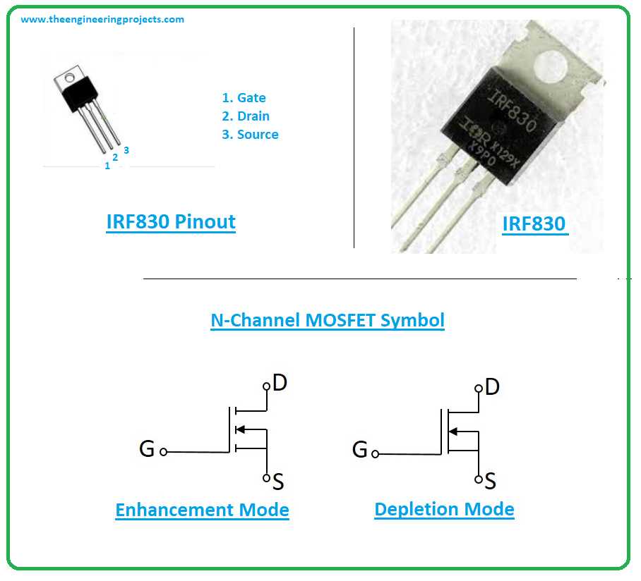
When exploring the world of electronic components, it is crucial to comprehend the intricacies of the P Mosfet datasheet. This valuable document encompasses vital information regarding the performance and characteristics of the P-channel metal-oxide-semiconductor field-effect transistor, without explicitly using the terms “mosfet” or “datasheet”. In this section, we will delve into the key specifications and parameters provided in the P Mosfet datasheet, shedding light on its importance for electrical engineers.
Understanding Voltage Ratings
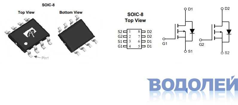
The P Mosfet datasheet offers a comprehensive breakdown of various voltage ratings, which play a significant role in determining the transistor’s operation and reliability. These ratings include the drain-source voltage (VDS) and the gate-source voltage (VGS), indicating the maximum voltages that the transistor can safely handle. Additionally, the datasheet presents the threshold voltage (VTH), defining the minimum voltage required to turn the transistor on, and the breakdown voltage (BVDS), indicating the voltage at which the transistor experiences irreversible damage. A thorough understanding of these voltage ratings is essential to ensure the P Mosfet’s optimal performance and longevity.
Examining Current Parameters
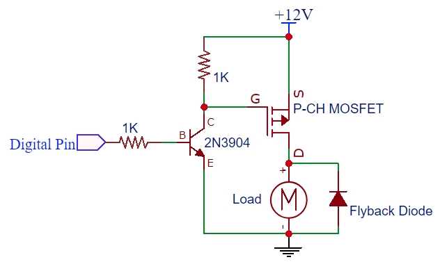
Another crucial aspect covered in the P Mosfet datasheet revolves around current parameters, which provide insights into the transistor’s current-handling capabilities. The datasheet includes details on the drain current (ID), indicating the maximum continuous current that the transistor can safely conduct. Additionally, the on-resistance (RDS(on)) specifies the resistance between the drain and source terminals when the transistor is fully turned on, affecting its power dissipation characteristics. Furthermore, the datasheet presents information on the gate threshold current (IGT), representing the minimum current required to activate the transistor. A thorough comprehension of these current parameters allows engineers to design reliable and efficient electronic circuits using P Mosfets.
Additional Specifications and Parameters
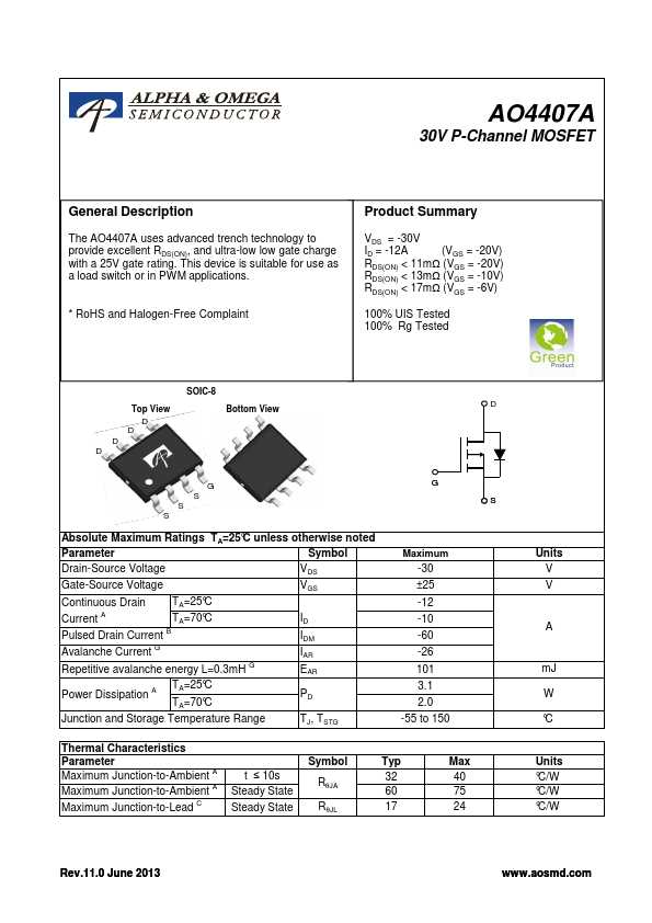
Beyond voltage and current parameters, the P Mosfet datasheet provides a plethora of additional specifications and parameters to aid in the transistor’s proper utilization. These include details on capacitances, such as the input capacitance (Ciss), output capacitance (Coss), and reverse transfer capacitance (Crss), which impact the transistor’s switching performance. Moreover, the datasheet offers information on thermal characteristics, such as junction-to-ambient thermal resistance (RθJA), enabling engineers to determine the transistor’s temperature limits. It also covers details on the gate charge (QG), providing insights into the transistor’s switching speed. By meticulously studying these specifications and parameters, engineers can leverage the full potential of the P Mosfet in their electronic designs.
In conclusion, the P Mosfet datasheet serves as a vital resource for electrical engineers, offering a wealth of information without directly mentioning the terms “mosfet” or “datasheet”. By understanding and interpreting the key specifications and parameters presented in the datasheet, engineers can effectively utilize P Mosfets in their designs, ensuring optimal performance and reliability.
Overview of P Mosfet
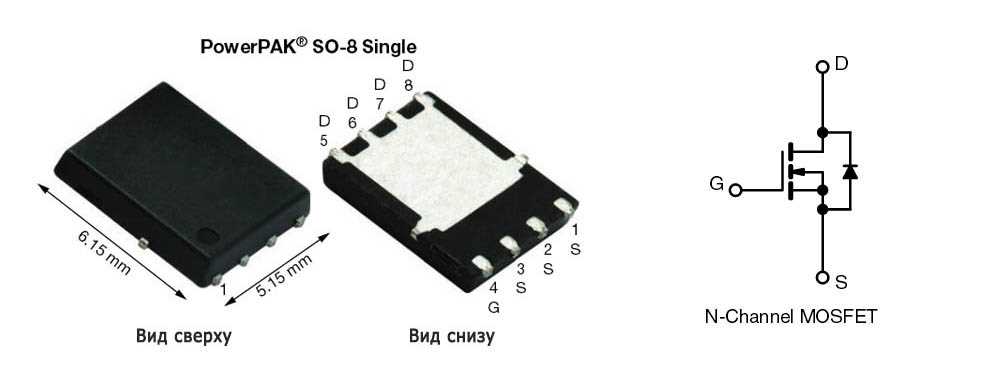
This section provides a comprehensive overview of the P-type Metal-Oxide-Semiconductor Field-Effect Transistor (P Mosfet), a crucial component in modern electronic devices.
The P Mosfet is an essential building block for a variety of applications, including power amplifiers, voltage regulators, and digital logic circuits. It operates by controlling the flow of current through a semiconductor channel, which is formed between the source and drain regions. Unlike its counterpart, the N Mosfet, the P Mosfet uses a positive voltage applied to the gate to control this current flow.
Understanding the characteristics and behavior of the P Mosfet is essential for designing efficient and reliable electronic circuits. By analyzing its operating principles, voltage-current relationships, and performance parameters, engineers can optimize the utilization of P Mosfets in their designs, ensuring proper functionality and performance.
In this overview, we will delve into the key aspects of P Mosfet operation, including the concept of threshold voltage, drain-source current characteristics, and the influence of temperature on device performance. Furthermore, we will explore the different modes of operation, such as cutoff, saturation, and linear region, and discuss their significance in various circuitry applications.
Additionally, this section will touch upon the various design considerations for P Mosfets, including input and output capacitances, output conductance, and gate charge. By understanding these parameters, engineers can accurately predict the behavior of P Mosfets in different circuit configurations, ensuring optimal performance and reliability.
Overall, this overview aims to provide a comprehensive understanding of the P Mosfet, enabling engineers and enthusiasts to effectively utilize this critical component in their electronic designs and facilitate the development of innovative and efficient electronic devices.
Key Specifications in P Mosfet Datasheet
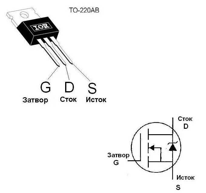
In this section, we will explore the essential specifications that can be found in a P Mosfet datasheet. These specifications provide critical information about the performance and capabilities of the P Mosfet, allowing engineers to select the right component for their specific application.
1. Drain-Source Voltage (VDS)
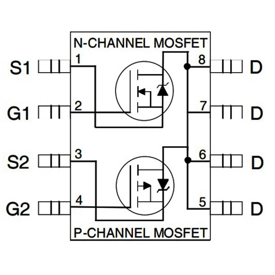
One of the key specifications provided in the P Mosfet datasheet is the maximum drain-source voltage (VDS) rating. This parameter indicates the maximum voltage that can be applied between the drain and source terminals without causing damage to the device. It is important to select a P Mosfet with a VDS rating that exceeds the maximum voltage expected in the circuit to ensure proper operation and reliability.
2. Drain Current (ID)

The drain current (ID) specification reveals the maximum current that the P Mosfet can handle without exceeding its thermal limits. It is crucial for engineers to ensure that the expected current in their circuit does not exceed the ID rating of the chosen P Mosfet, as exceeding this limit can lead to overheating and potential failure of the component.
These key specifications, along with several others, such as gate threshold voltage, on-state resistance, and capacitances, provide important information to engineers to make informed decisions when selecting a P Mosfet for their design. Understanding these specifications and their significance is crucial for ensuring optimal performance and reliability in various applications.
Interpreting P Mosfet Datasheet: Parameters and Characteristic Curves

Understanding the essential details of a P MOSFET’s datasheet is crucial for its proper utilization and application in electrical circuits. By comprehending the parameters and characteristic curves provided, one gains valuable insights into the device’s performance and limitations. This section delves into the key aspects to consider when interpreting a P MOSFET datasheet, facilitating informed decision-making and optimized circuit designs.
Threshold Voltage: An essential parameter, often denoted as VTH, delineates the voltage at which the P MOSFET switches from its default OFF state to an ON state. It signifies the minimum input voltage required to control the device’s conduction, and understanding this threshold ensures accurate circuit operation.
Drain-Source Breakdown Voltage: Indicated as VDS(BR), this parameter delineates the maximum voltage that can be applied between the drain and source terminals of a P MOSFET without causing breakdown or damage to the device. It ensures reliable operation under various voltage conditions and safeguards against voltage spikes.
Transconductance: Represented by the symbol “gfs,” transconductance characterizes the relationship between the input voltage and the resulting drain current. It provides insights into the device’s amplification capabilities and is a crucial factor in circuits involving signal processing and amplification.
Drain-Source Resistance: Denoted as RDS(ON), this parameter signifies the resistance between the drain and source terminals when the MOSFET is in its fully ON state. A lower value indicates reduced power dissipation and higher efficiency. Understanding this resistance allows for appropriate thermal management and ensures optimum performance in power applications.
Gate Charge: Gate charge, often represented as QG, illustrates the amount of charge required to fully enhance the MOSFET’s conduction when transitioning from an OFF state to an ON state. It affects switching speed, with higher gate charge contributing to longer switching times. An understanding of this parameter assists in choosing appropriate driving circuits and ensures efficient switching performance.
Characteristic Curves: Alongside numerical parameters, P MOSFET datasheets often present characteristic curves that depict the device’s performance over a range of operating conditions. These curves enable engineers to visually analyze the MOSFET’s behavior, including its output characteristics, transfer characteristics, and significant regions of operation. Understanding these curves aids in circuit design and verification, ensuring optimal utilization of the P MOSFET in various applications.
In conclusion, a P MOSFET datasheet comprises crucial parameters and characteristic curves that reveal essential insights into the device’s behavior. By effectively interpreting and analyzing these details, engineers can make informed decisions regarding the MOSFET’s application, ensuring efficient circuit designs and reliable performance.