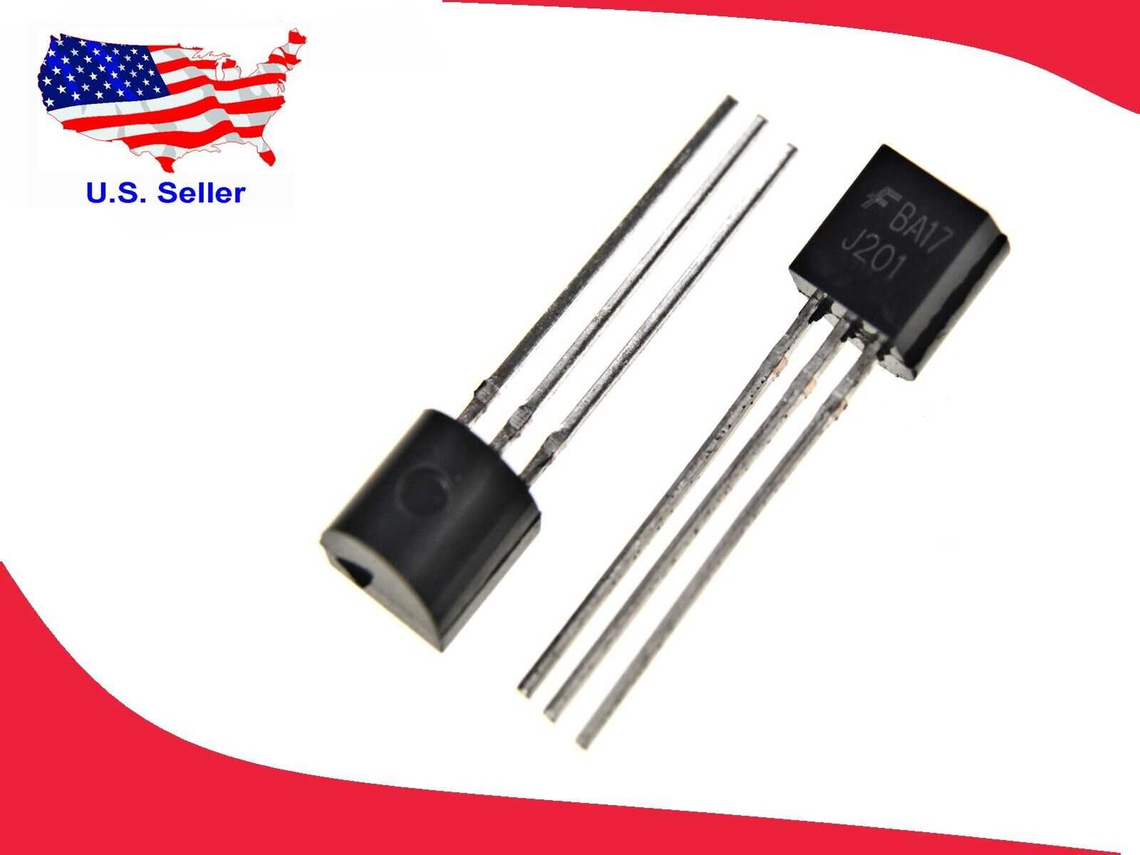
Welcome to the world of electronic components where innovation and functionality come together to shape the future of technology. In this article, we will explore a fascinating semiconductor device known for its versatile applications and reliable performance. We invite you to delve into the intricacies of the J201 JFET, a remarkable electronic component that has made its mark in numerous industries.
As we embark on this journey, we will unravel the mysteries behind the J201 JFET. This small yet powerful device has proved its mettle in amplification and switching circuits, providing engineers and enthusiasts with a reliable solution for various electronic projects. Through comprehensive research and analysis of its datasheet, we will gain insights into the specifications, characteristics, and operating principles of the J201 JFET.
Discover the exceptional capabilities of this device that enable it to function as a voltage-controlled resistor, opening up a whole realm of possibilities for circuit design. Unveil the secrets behind its unique structure and gain a deeper understanding of how it interacts with electrical signals to deliver the desired outcomes. By grasping the fundamentals of the J201 JFET, you will have a solid foundation to unleash your creativity and create cutting-edge electronic systems.
The Basics of J201 JFET: A Comprehensive Datasheet Overview
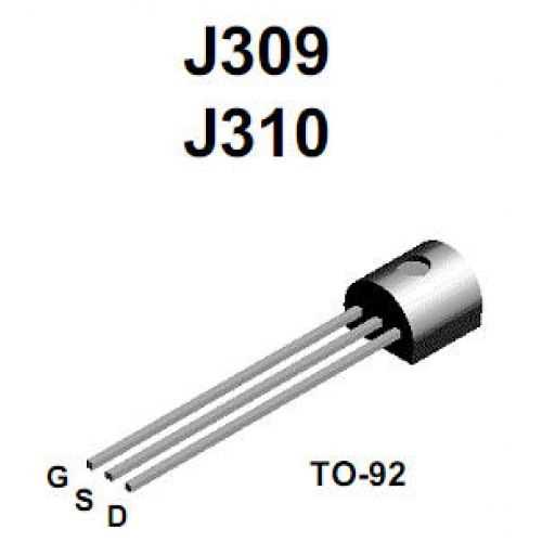
In this section, we will provide a comprehensive overview of the J201 JFET, a widely used component in electronic circuits. We will explore its fundamental properties and applications without directly referencing the specific product specifications. By delving into the principles and characteristics underlying the J201 JFET, we aim to offer readers a broad understanding of this key electronic component.
Introduction to J201 JFET
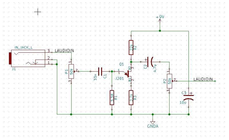
At the core of many electronic devices and applications, the J201 JFET plays a crucial role in signal amplification and control. This type of field-effect transistor operates by utilizing the conductivity modulation characteristics of a channel formed between the source and drain regions. Understanding the basic principles of JFET operation is essential for grasping its wide range of applications in the field of electronics.
JFET Construction and Operation
The construction of a JFET primarily involves three main regions: the source, the drain, and the channel. By applying appropriate voltages, the channel conductivity is modulated, allowing for precise control of the current flowing through the device. A thorough understanding of the intricate interplay between the source, drain, and channel is necessary to fully comprehend the operational principles of the J201 JFET.
As we delve deeper into the operational characteristics and applications of the J201 JFET, we will explore concepts such as voltage-controlled resistance, transconductance, cutoff frequency, and the relationship between biasing and performance. By gaining a comprehensive understanding of these fundamental principles, readers will be better equipped to utilize the J201 JFET in various electronic circuit designs and applications.
Understanding the J201 JFET: Structure, Characteristics, and Applications
In this section, we will explore the intricate details of the J201 JFET, a widely-used electronic component that plays a crucial role in various applications. By delving into its structure, characteristics, and applications, we can gain a comprehensive understanding of the J201 JFET’s functionality and its significance in modern electronic circuits.
Structure:
The J201 JFET’s structure consists of a channel made of semiconductor material, allowing the flow of current between its source and drain terminals. It possesses a gate terminal that controls the current flow by altering the electric field within the channel. The J201 JFET can be categorized as a depletion mode JFET, meaning that it operates with a conductive channel in its natural state, with the gate voltage causing a decrease in conductivity.
Characteristics:
One of the notable characteristics of the J201 JFET is its high input impedance, which enables it to minimize the loading effect on the preceding circuitry. Additionally, it exhibits a significant voltage gain, making it suitable for amplification purposes. The J201 JFET also possesses low noise characteristics, a wide operating temperature range, and excellent linearity, contributing to its versatility in various electronic applications.
Applications:
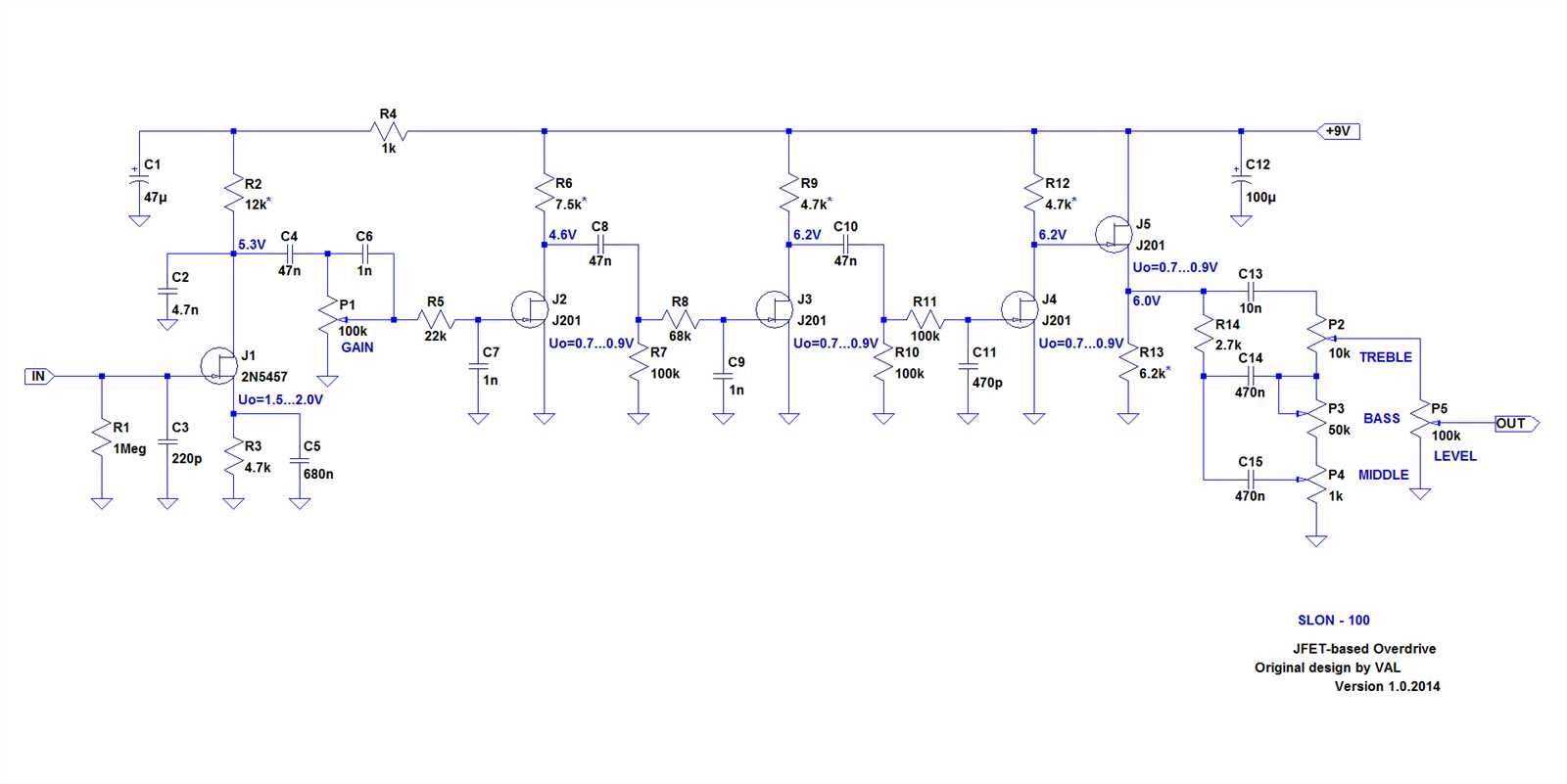
The J201 JFET finds extensive use in the field of audio engineering, where it is employed in preamplifiers, equalizers, and audio mixers. Its low noise performance and high input impedance make it an ideal choice for audio signal processing, ensuring clean and accurate audio reproduction. Additionally, the J201 JFET is utilized in analog switches, voltage-controlled resistors, and current sources.
By comprehending the structure, characteristics, and applications of the J201 JFET, we can harness its potential in designing electronic circuits for a wide range of purposes. Its unique attributes enable engineers and hobbyists to achieve efficient signal amplification and processing, making it a valuable component in the world of electronics.
Exploring the Electrical Specifications of J201 JFET: Voltage, Current, and Power Ratings
Delving into the intricate details of the electrical specifications of the J201 junction field-effect transistor (JFET), we uncover valuable insights into its voltage, current, and power ratings. By thoroughly examining these specifications, we gain a comprehensive understanding of the performance capabilities and limits of this electronic component.
One fundamental aspect to explore is the voltage rating of the J201 JFET. This specification indicates the maximum voltage that can be applied across the component without causing irreversible damage. Understanding this rating is crucial when designing circuits to ensure that the J201 operates within its safe voltage range, preventing possible breakdowns or failures.
Another key specification to examine is the current rating of the J201 JFET. This rating defines the maximum current that can flow through the component without causing excessive heating or compromising its overall performance. By adhering to this specification, we can effectively measure and control the current passing through the J201, ensuring proper functionality and preventing potential malfunctions.
Additionally, the power rating of the J201 JFET is an essential factor to consider. This specification outlines the maximum power dissipation capability of the component, indicating the amount of power it can handle without surpassing its thermal limitations. By taking into account the power rating, we can accurately design circuits that optimize the J201’s usage while minimizing the risk of overheating or damage.
Exploring these electrical specifications of the J201 JFET empowers engineers and electronics enthusiasts to make informed decisions when incorporating this component into their designs. By understanding the voltage, current, and power ratings, one can ensure proper operation and enhance the overall performance and reliability of electronic circuits utilizing the J201 JFET.
Performance and Limitations: Analyzing the Typical Performance Curves and Noise Parameters of J201 JFET
The performance of J201 JFET, a type of field-effect transistor, is essential to understand for its effective and efficient use in electronic circuits. This section aims to analyze the typical performance curves and noise parameters associated with the J201 JFET, providing valuable insights into its capabilities and limitations.
Performance curves, also known as characteristic curves, provide a graphical representation of the J201 JFET’s behavior under different operating conditions. These curves illustrate critical parameters such as drain current versus gate-source voltage and transfer characteristics. By analyzing these curves, engineers can determine the JFET’s stability, linearity, and operating regions.
In addition to performance curves, noise parameters play a significant role in evaluating the J201 JFET’s overall performance. Noise parameters refer to the electrical noise generated within the JFET itself and its impact on the desired signal. These parameters include noise figure, noise voltage, and noise current. Understanding the noise parameters allows engineers to design circuits that minimize noise and maximize signal integrity.
By analyzing the typical performance curves and noise parameters of the J201 JFET, engineers can make informed decisions about its suitability for various applications. These parameters help in determining the JFET’s gain, distortion, bandwidth, and noise characteristics, enabling the design and optimization of circuits for specific requirements.
It is important to note that while the J201 JFET offers several advantages, it also has limitations. These limitations may include variations in performance from one device to another, sensitivity to temperature changes, and limited voltage and current ratings. Engineers must consider these limitations when selecting and implementing the J201 JFET in their designs to ensure optimal performance and reliability.
In conclusion, analyzing the typical performance curves and noise parameters of the J201 JFET provides valuable insights into its capabilities and limitations. This analysis aids in understanding the JFET’s behavior under various operating conditions, allowing for informed design decisions and optimization of electronic circuits.