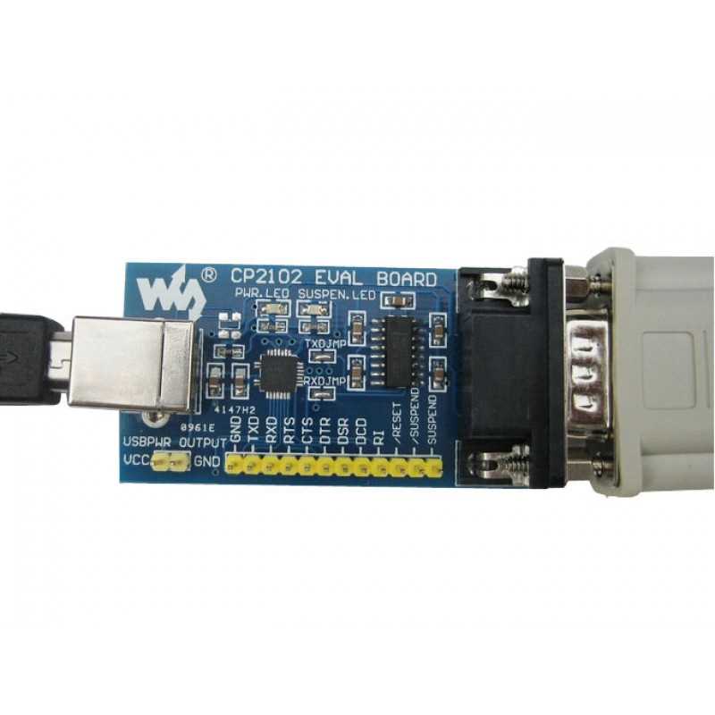
In the realm of modern technology, innovation and advancement are the driving forces behind every breakthrough. One such remarkable invention, worthy of our attention, is the intricate yet versatile circuit board known as the CP2102. This small yet mighty marvel is the key to achieving seamless connectivity and unlocking a world of endless possibilities.
Introducing the CP2102:
From enhancing communication between devices to enabling efficient data transfer, the CP2102 circuit board has revolutionized the way we connect and interact. It acts as a bridge, effortlessly facilitating the exchange of information, while ensuring a secure and stable connection that forms the backbone of countless technological applications.
Powerful Functionality:
The CP2102 circuit board is a manifestation of cutting-edge engineering and ingenuity. Its intelligent design encompasses a range of features that make it the go-to solution for various industries. Whether it is industrial automation, consumer electronics, or Internet of Things (IoT) applications, the CP2102 offers unparalleled functionality that enables seamless integration and optimizes performance.
Simplify Your Workflow:
While the technical details surrounding the CP2102 are complex and precise, its purpose is refreshingly simple – to streamline and simplify your workflow. By seamlessly connecting disparate devices and enabling efficient data transfer, this circuit board empowers users to focus on what truly matters – achieving their goals and bringing their ideas to life.
Understanding the cp2102 Datasheet
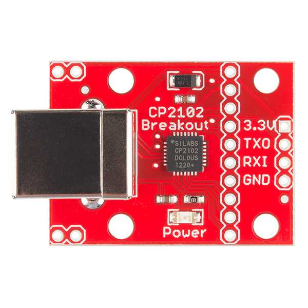
In this section, we will delve into an in-depth understanding of the technical documentation provided in the cp2102 datasheet. By comprehending the information presented, we can gain insight into the functionality and capabilities of this versatile device.
Overview of the cp2102 Datasheet
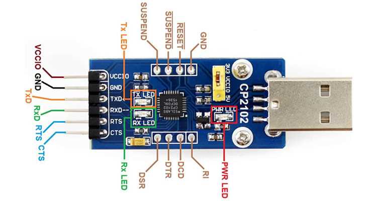
The cp2102 datasheet serves as a comprehensive resource that details the specifications, features, and application-specific information of the cp2102 device. It provides a comprehensive overview of the device’s key components, pin descriptions, and electrical characteristics, allowing users to fully comprehend its capabilities and design considerations.
Interpreting Key Terminology
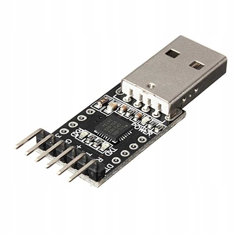
When analyzing the cp2102 datasheet, it is crucial to grasp the meaning of the technical terms and jargon used. This section will elucidate the terminology used in the datasheet, ensuring that readers have a solid foundation and can accurately interpret the information presented.
Understanding Device Functionality
By carefully studying the cp2102 datasheet, we can gain a clear understanding of the various functionalities and features that this device offers. It provides valuable insights into how the cp2102 operates, its communication protocols, and the supported baud rates, enabling developers and engineers to harness its full potential.
Ensuring Design Compatibility
One of the critical aspects of the cp2102 datasheet is its emphasis on design considerations and compatibility. By thoroughly examining this section, designers can comprehend the necessary guidelines and recommendations to ensure seamless integration of the cp2102 device into their hardware or software systems.
In conclusion, a comprehensive understanding of the cp2102 datasheet enables users to leverage the full capabilities of this powerful device. By delving into the technical documentation and interpreting key information, designers and engineers can successfully incorporate the cp2102 into their projects, ensuring optimal performance and functionality.
Key Features of cp2102
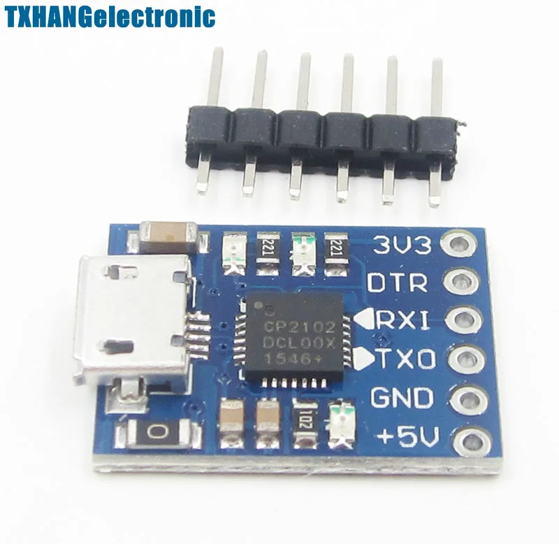
The cp2102 is a highly versatile and advanced integrated circuit that offers a multitude of features to enhance its functionality and reliability. This section aims to highlight the key attributes of the cp2102 without explicitly mentioning its name or referring to its datasheet.
One of the standout characteristics of this integrated circuit is its exceptional performance and robustness. It is designed to deliver reliable and efficient operation in various applications, ensuring high-quality data transmission. Furthermore, the cp2102 offers a wide range of connectivity options, allowing seamless integration with different devices and systems.
Another noteworthy feature of the cp2102 is its flexibility and adaptability. It supports different data rates and signal formats, enabling compatibility with diverse protocols and standards. This versatility makes it suitable for a wide array of applications, from consumer electronics to industrial automation.
In addition, the cp2102 boasts advanced power management capabilities, optimizing energy consumption and extending battery life in portable devices. It is also equipped with built-in protection mechanisms to safeguard against overvoltage, overcurrent, and other potential risks, ensuring the longevity and reliability of the system.
Moreover, the cp2102 offers seamless integration with various operating systems, providing drivers and software support for effortless installation and configuration. This simplifies the development process and facilitates quick deployment of the integrated circuit in different environments.
Overall, the cp2102 stands out for its exceptional performance, versatility, and robustness. With its wide range of features and capabilities, it serves as a reliable and efficient solution for diverse applications, making it an ideal choice for developers and engineers.
cp2102: Pin Description and Functionality
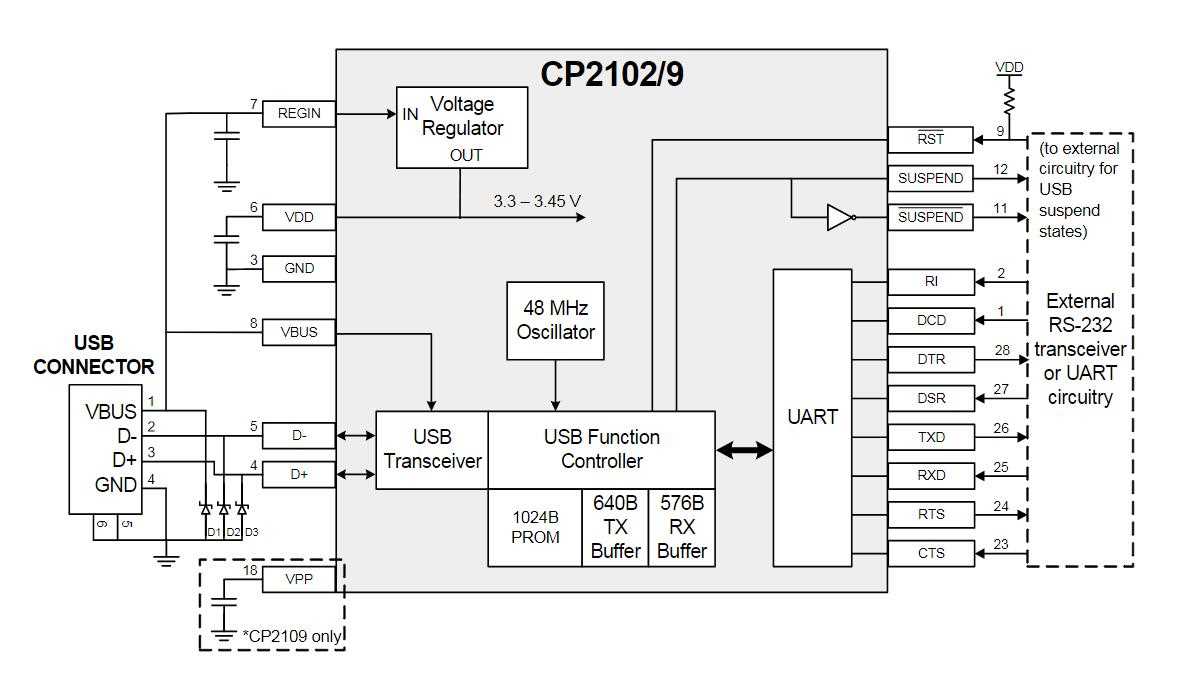
In this section, we will explore the pin description and functionality of the cp2102, a widely used integrated circuit. Understanding the different pins and their functions is crucial for effectively utilizing the capabilities of the cp2102 in various applications. Let’s dive into the details!
1. Pin 1 – VDD: This pin provides the power supply voltage for the cp2102. It is typically connected to a 3.3V or 5V power source, depending on the specific requirements of the application.
2. Pin 2 – GND: This pin is the ground reference for the cp2102 and should be connected to the ground of the system.
3. Pin 3 – TXD: The data transmitted from the cp2102 to the external device is output through this pin. It can be connected to the receive (RX) pin of a microcontroller or other receiving devices.
4. Pin 4 – RXD: This pin receives data from an external device and is connected to the transmit (TX) pin of a microcontroller or other transmitting devices.
5. Pin 5 – RTS: The Request To Send (RTS) pin is used for flow control in serial communication. It is typically connected to the Clear To Send (CTS) pin of the external device.
6. Pin 6 – CTS: The Clear To Send (CTS) pin is used for flow control in serial communication. It is typically connected to the Request To Send (RTS) pin of the external device.
7. Pin 7 – DTR: The Data Terminal Ready (DTR) pin is used for signaling the readiness of the cp2102 to communicate with an external device.
8. Pin 8 – DSR: The Data Set Ready (DSR) pin indicates that the external device connected to the cp2102 is ready to communicate.
9. Pin 9 – RI: The Ring Indicator (RI) pin is used to indicate an incoming call or other event from the external device.
10. Pin 10 – DCD: The Data Carrier Detect (DCD) pin detects the presence of a carrier signal from the external device.
The cp2102 offers a range of features and functionalities through its various pins, allowing for versatile usage in a wide range of applications. Understanding these pin descriptions and functionalities is essential for successful integration and utilization of the cp2102 in different projects.
Exploring the Pinout of cp2102
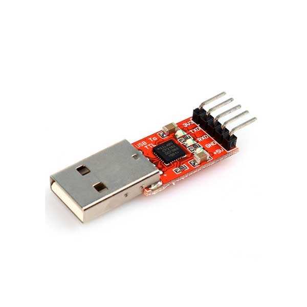
In this section, we will delve into the pinout configuration of the cp2102, a versatile USB to UART bridge controller. Understanding the pinout layout is crucial for properly connecting and utilizing this powerful device in various applications.
The pinout of the cp2102 consists of a number of pins, each serving a unique purpose. By examining the function of these pins and their respective connections, we can gain a comprehensive understanding of the capabilities and potential applications of the cp2102.
A closer look at the pinout reveals that the cp2102 features multiple UART interface pins, as well as pins for power supply and ground connections. Additionally, there are pins dedicated to controlling the device, such as the reset pin and the GPIO pins, which can be used for various purposes depending on the specific needs of the application.
By connecting the appropriate peripheral devices or components to the different pins, users can interface the cp2102 with a variety of systems and devices, unlocking its full potential. It is important to carefully study the pinout configuration and refer to the documentation for accurate pin assignments and voltage requirements.
- UART interface pins allow for bidirectional communication between the cp2102 and external devices.
- Power supply and ground pins provide the necessary electrical connection for the cp2102 to function properly.
- The reset pin allows for resetting the cp2102, while the GPIO pins offer additional control and flexibility.
- Understanding the pinout will enable users to make the most out of the cp2102 and implement it effectively in their projects.
Overall, a thorough exploration of the pinout of the cp2102 is crucial for understanding its capabilities and potential applications. By connecting the appropriate devices and components to the various pins, users can harness the power of this USB to UART bridge controller for a wide range of projects and systems.
Understanding the Functionality of Each Pin
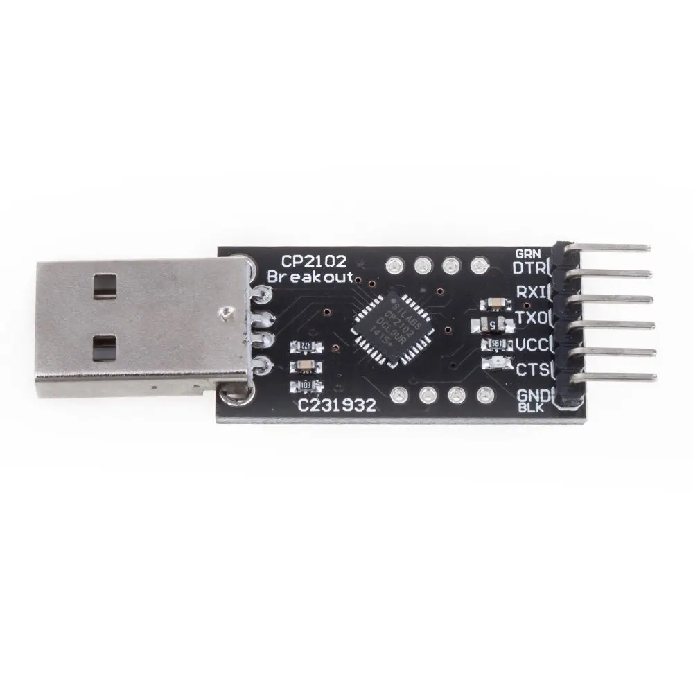
In this section, we will delve into the various pins of the CP2102 chip and explore their individual functions. By gaining a clear understanding of the purpose and capabilities of each pin, we can effectively utilize the features offered by this versatile device.
1. Power Pins
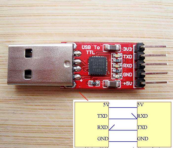
The CP2102 includes several power pins that play a crucial role in providing the necessary electrical energy for the chip’s operation. These pins typically include VCC, VDD, and GND, which respectively serve as the positive supply voltage, digital supply voltage, and ground connection. It is essential to ensure a stable and appropriate power supply to prevent any malfunctions or damage to the chip.
2. Communication Pins
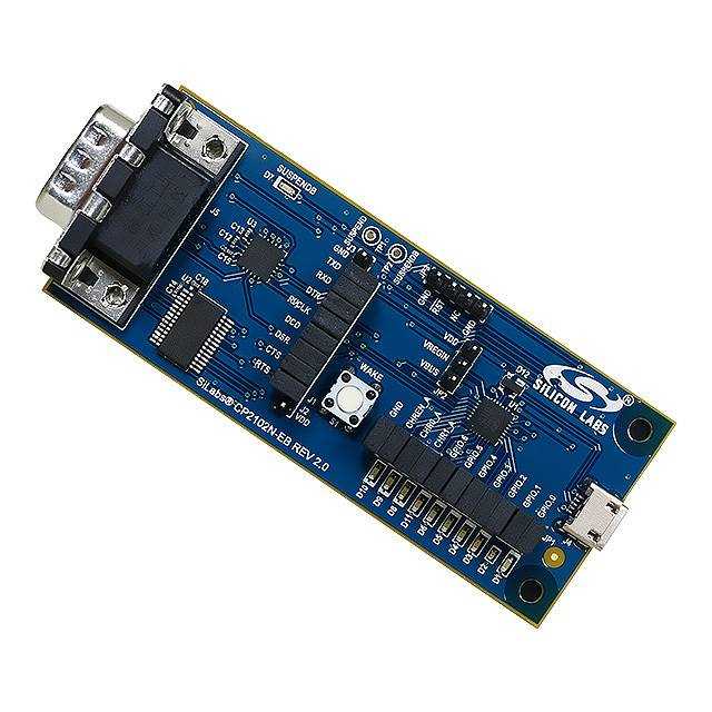
Another set of pins on the CP2102 chip is dedicated to communication purposes. These pins facilitate the transfer of data between the chip and other devices, such as microcontrollers or computers. Examples of these communication pins include TXD (Transmit Data) and RXD (Receive Data), which enable serial communication. These pins allow for the exchange of information, making the CP2102 an excellent choice for applications requiring seamless data transfer.
Additionally, the CP2102 may feature pins that support other communication protocols, such as I2C or SPI. These pins provide flexibility in connecting the chip to different devices and expanding its usability in a wide range of applications.
Overall, understanding the functionality of each pin on the CP2102 chip is crucial for harnessing its full potential in various electronic projects. By being aware of the power and communication capabilities of each pin, developers can effectively integrate the CP2102 into their designs, enabling seamless data transfer and efficient operation.