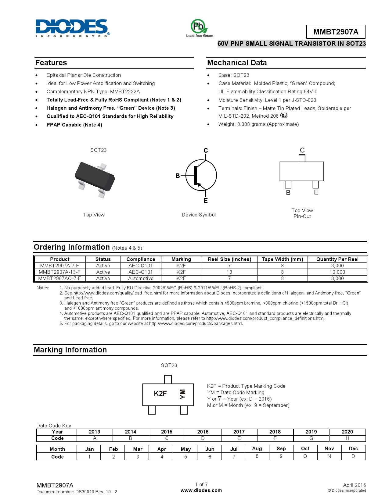
Are you a tech enthusiast looking to dive into the world of electronic components? If so, then look no further than the phenomenal Pn2907. This remarkable device boasts an array of functionalities that make it a must-have in any electrical engineering arsenal. In this comprehensive guide, we will explore the intricacies of this cutting-edge component, uncovering its diverse applications and uncovering the secrets behind its unparalleled performance.
With its superior design and unparalleled performance, the Pn2907 epitomizes excellence in the world of electronic components. This versatile device serves as a crucial building block in a multitude of circuits, lending its prowess in amplification, switching, and signal conditioning. Its compact size and remarkable efficiency make it an invaluable asset in a wide range of applications, from consumer electronics to aerospace engineering.
At the heart of the Pn2907 lies a symphony of ingenuity and innovation. Equipped with state-of-the-art technology, this component delivers exceptional performance while maintaining a remarkably low power consumption. Its robust design ensures reliable operation even in the harshest of environments, making it a go-to choice for engineers seeking a reliable solution for their projects.
The Basics of Pn2907 Datasheet: Understanding the Specifications

When delving into the intricacies of the Pn2907 datasheet, it is essential to first comprehend the underlying specifications. These specifications serve as a roadmap, providing valuable insights into the characteristics and functionalities of the Pn2907 transistor.
Understanding Key Parameters
One of the fundamental aspects of interpreting the Pn2907 datasheet lies in grasping the essential parameters that define its performance. These parameters highlight crucial details such as voltage ratings, current flows, gain values, and frequency response. By examining these specifications, engineers can determine the transistor’s suitability for specific applications, enabling them to make informed design decisions.
Voltage Ratings and Current Flows
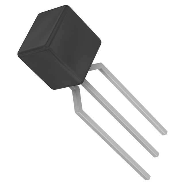
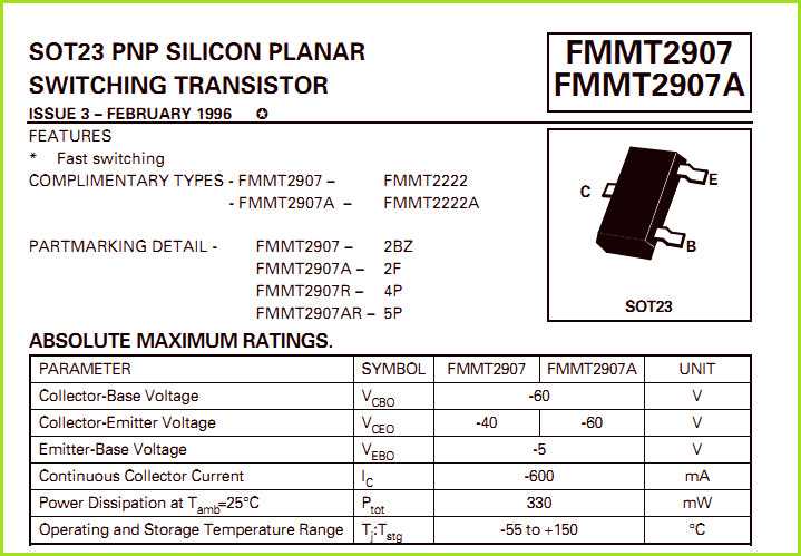
The Pn2907 datasheet outlines the voltage ratings that dictate the maximum voltages the transistor can handle without compromising its functionality. These ratings include the collector-emitter voltage (VCEO), collector-base voltage (VCBO), and emitter-base voltage (VEBO). Additionally, the datasheet provides details regarding the maximum current flows for both continuous and peak conditions, shedding light on the transistor’s robustness and stability.
Gain Values and Frequency Response
An important consideration while evaluating the Pn2907 datasheet is the gain values, which indicate the amplification capability of the transistor. The datasheet provides information on both the DC current gain (hFE) and the small-signal current gain (hfe). These values aid in analyzing the signal amplification characteristics of the transistor, enabling engineers to assess its performance in various circuits and applications. Furthermore, the datasheet offers insights into the frequency response, illustrating the transistor’s ability to handle signals at different frequencies without distortion.
By comprehending the specifications outlined in the Pn2907 datasheet, engineers gain vital knowledge that assists in realizing the transistor’s potential and optimizing its usage in diverse electronic applications.
Exploring the Key Features and Electrical Characteristics
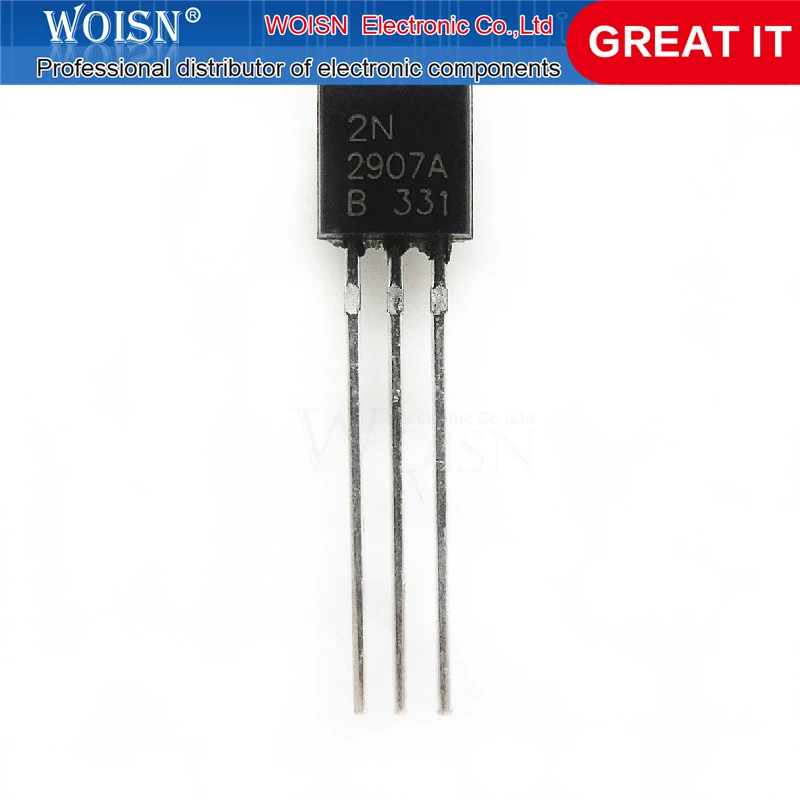
In this section, we will delve into the essential aspects of the Pn2907 transistor, examining its unique qualities and important electrical attributes. By understanding its key features and exploring its electrical characteristics, we can gain insight into the capabilities and applications of this versatile component.
Firstly, let us focus on the distinctive attributes that set the Pn2907 apart from other transistors. This component exhibits remarkable performance in terms of amplification, enabling it to augment electrical signals with precision and efficiency. Additionally, the Pn2907 showcases outstanding voltage capability, accommodating a wide range of input and output voltages, making it adaptable to various circuit requirements.
One of the notable characteristics of the Pn2907 transistor is its exceptional current gain. With a high current gain, this component facilitates the amplification of weak input currents to produce more robust output currents, strengthening the overall signal integrity. Moreover, the Pn2907 exhibits low noise characteristics, ensuring minimal distortion and interference in signal transmission.
Another significant feature worth exploring is the Pn2907 transistor’s temperature stability. This component demonstrates excellent thermal performance, allowing it to maintain consistent functionality even in demanding environmental conditions. This attribute proves particularly useful in applications that involve elevated temperatures or fluctuating thermal conditions.
Furthermore, the Pn2907 transistor boasts a compact and space-efficient design, ideal for applications where board space is limited. Its small footprint does not compromise its performance or reliability, making it a valuable choice for compact electronic devices. Moreover, the Pn2907 is available in various package options, allowing for flexible integration into diverse circuit designs.
Overall, by exploring the key features and electrical characteristics of the Pn2907 transistor, we can appreciate its versatile nature and suitability for a wide range of electronic applications. Its exceptional amplification capabilities, voltage capability, high current gain, low noise characteristics, temperature stability, and compact design make it a valuable component in numerous circuit designs.
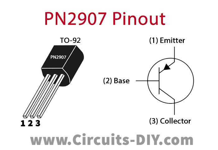
Understanding the Pin Configuration and Functionality
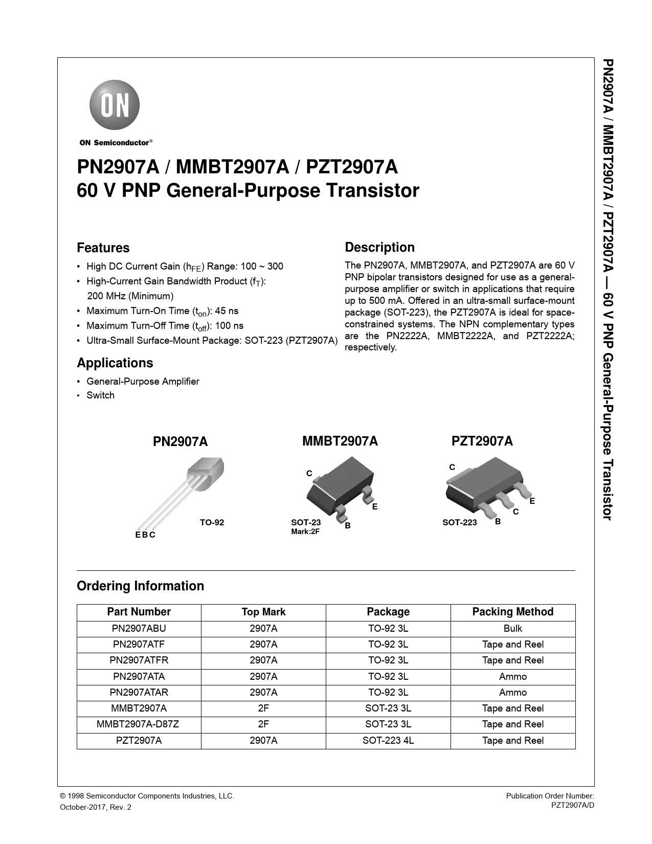
In this section, we will explore the pin configuration and functionality of a certain electronic component. By understanding how each pin is connected and its corresponding functionality, we can gain a deeper understanding of how the component works and how it can be used in various applications.
Pin Configuration
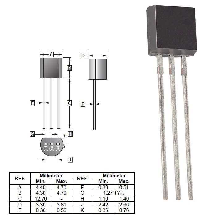
The pin configuration refers to the physical layout of the component’s pins. Each pin is assigned a specific number or label that corresponds to its function. By referring to the pin configuration diagram or table, we can easily identify the purpose of each pin and its location on the component.
Functionality
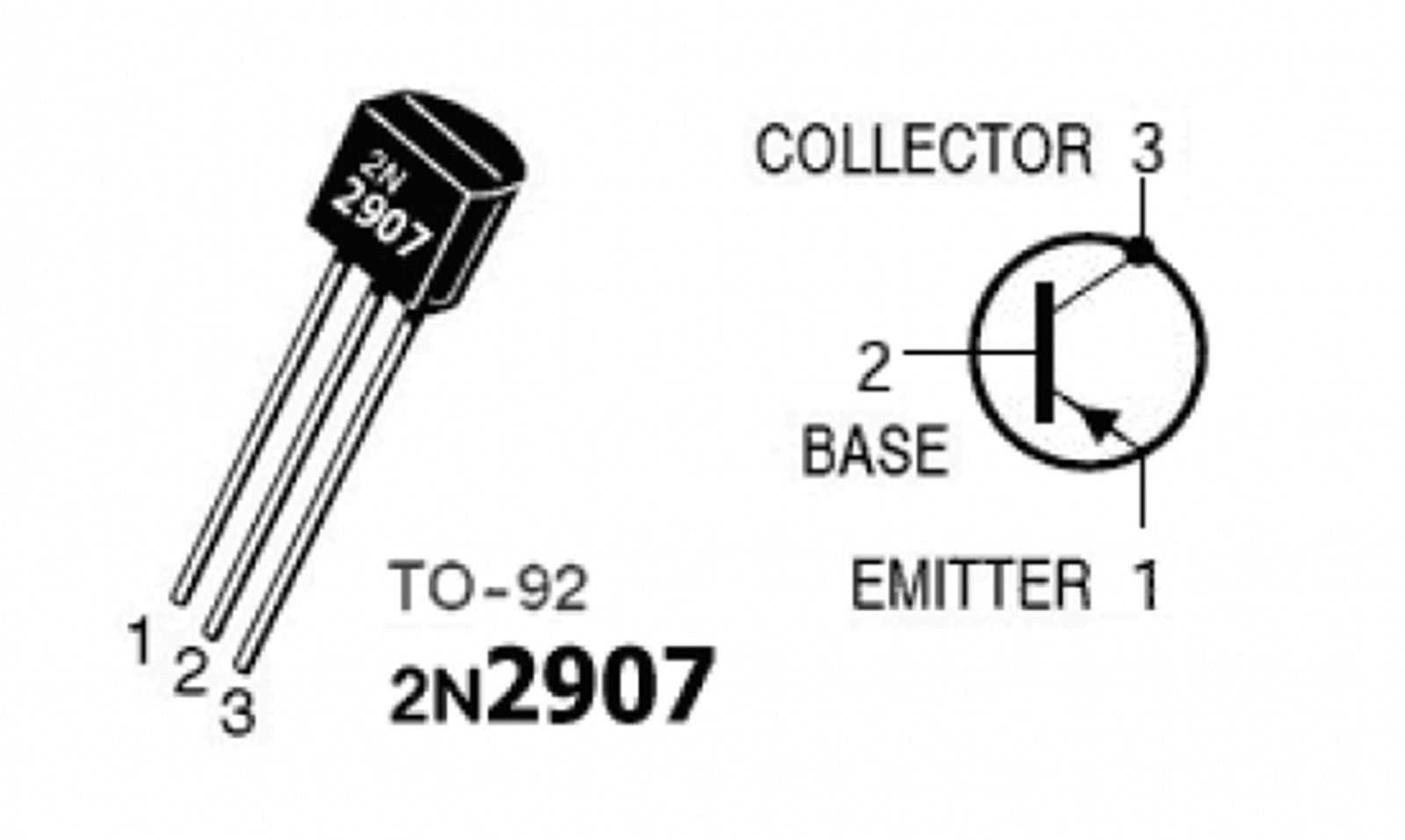
The functionality of each pin determines its role in the overall operation of the component. Some pins may be responsible for inputting signals or data, while others may be used for outputting signals or power. Understanding the functionality of each pin is crucial for proper integration of the component into a circuit or system.
To further explore the pin configuration and functionality, let’s take a look at the following table:
| Pin Number | Function |
|---|---|
| 1 | Ground |
| 2 | Input Signal |
| 3 | Output Signal |
| 4 | Power Supply |
In the above table, we can see that pin number 1 is designated for the ground connection, which ensures proper grounding of the component. Pin number 2 serves as an input for a signal or data, allowing the component to receive external information. Pin number 3 acts as an output for a signal or data, enabling the component to transmit information to other parts of a circuit or system. Finally, pin number 4 is responsible for supplying power to the component, ensuring its proper functioning.
By understanding the pin configuration and functionality of this electronic component, we can effectively utilize it in various electronic applications, allowing us to design and build more sophisticated and efficient systems.
How to Interpret Pn2907 Datasheet: A Comprehensive Guide
In order to fully understand the specifications and characteristics of the Pn2907 component, it is essential to accurately interpret the accompanying documentation. This comprehensive guide will provide you with the necessary insights and tips to effectively analyze and make informed decisions based on the information provided in the Pn2907 datasheet.
Understanding Key Specifications
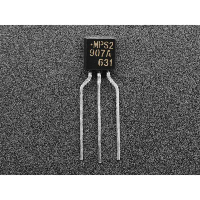
When examining the datasheet, it’s vital to focus on the key specifications that determine the performance and functionality of the Pn2907 component. Pay close attention to parameters such as voltage ratings, current capacities, and frequency ranges, as they directly impact the suitability of the component for your specific application. An in-depth understanding of these specifications will enable you to make well-informed decisions during circuit design or component selection processes.
Analyzing Graphs and Diagrams
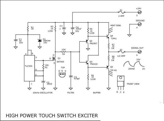
Graphical representations and diagrams in the Pn2907 datasheet provide valuable insights into the behavior and characteristics of the component. These visual aids offer a convenient way to comprehend the performance of the component under different conditions or input variables. Analyze the graphs and diagrams to understand the relationships between parameters and their corresponding values. Pay particular attention to trends, ranges, and limitations illustrated by these representations, as they offer practical guidance for optimizing circuit performance.
Pro Tip: When studying graphs, look for inflection points, saturation regions, or any other critical points that can impact the behavior of the Pn2907 component. These points often correspond to specific operating conditions or limitations that must be considered when designing circuits or making decisions related to the component’s usage.
Additionally, make use of the supporting information provided alongside the graphs, as it can offer further clarity or specific details about the performance characteristics being depicted.
In conclusion, by comprehensively interpreting the Pn2907 datasheet, you will gain valuable insights into the component’s specifications, behavior, and limitations. This in-depth understanding will empower you to effectively select, integrate, and optimize the Pn2907 component within your circuits, leading to enhanced performance and successful project outcomes.
Decoding the Electrical Ratings and Absolute Maximum Ratings
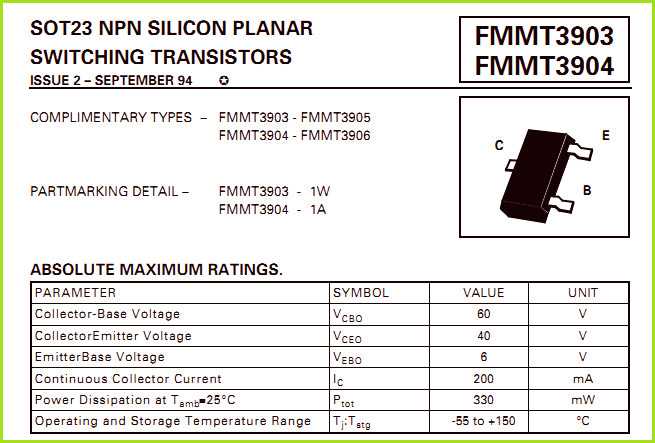
In the realm of electronic components, decoding the electrical ratings and absolute maximum ratings is of utmost importance for proper and safe usage. Understanding the limitations and specifications of a component ensures that it will operate within its designated parameters, preventing damage or failure in a circuit.
Electrical ratings refer to the specific values that a component can handle or provide in terms of voltage, current, power, and frequency. These ratings establish the boundaries within which the component can function effectively, ensuring optimal performance. It is vital to grasp these ratings to guarantee compatibility and avoid overloading or suboptimal functioning.
Absolute maximum ratings, on the other hand, define the extreme limits beyond which a component should never be operated. These values indicate the maximum voltages, currents, powers, temperatures, and other parameters that a component can withstand without risking permanent damage or failure. Operating a component beyond these limits can result in irreversible consequences that render the component useless.
By properly decoding electrical ratings and absolute maximum ratings, designers and engineers can make informed decisions regarding the selection and utilization of electronic components. They can assess the compatibility of components with a given circuit, calculate the required power and voltage levels, and ensure that all components remain within safe operating conditions.
It is crucial to remember that electrical ratings and absolute maximum ratings vary across different components and should be carefully considered for each specific case. Merely relying on assumptions or disregarding these ratings can lead to circuit malfunctions, damage to components, or even hazardous situations.
Overall, comprehending and interpreting the electrical ratings and absolute maximum ratings play a fundamental role in effective circuit design, safe component usage, and reliable electronic systems.