In the vast field of electronics, the successful design and implementation of any circuit board requires a thorough understanding of the numerous components that make up its intricate framework. One such component, often encountered but frequently overlooked, is a small but indispensable component known as a 0.1 uF SMD capacitor.
These tiny devices, present in almost every electronic gadget and device, serve a vital purpose in filtering unwanted noise and stabilizing voltage levels within a circuit. However, before using them in a project, it is critical to examine their datasheets closely to fully comprehend their capabilities and limitations.
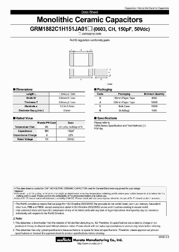
By delving into the intricate details of a 0.1 uF SMD capacitor datasheet, engineers and electronics enthusiasts can unlock a wealth of information that will aid them in optimizing the performance of their projects. From understanding the capacitance value and its impact on circuit behavior to grasping the various physical characteristics, such as package size and mounting considerations, these datasheets provide a comprehensive overview of all the essential facts one needs to know about these capacitors.
Understanding the 0.1 uF SMD Capacitor Datasheet
Exploring the intricacies of the information presented in a datasheet is crucial for engineers and electronics enthusiasts when working with electronic components. In this article, we will delve into the details of the datasheet for a 0.1 uF surface mount device (SMD) capacitor, providing a comprehensive understanding of its specifications and parameters.
Interpreting the Electrical Parameters
When analyzing the datasheet of a 0.1 uF SMD capacitor, several key electrical parameters come into play. These parameters provide essential insights into the capacitor’s performance and compatibility with different applications. Capacitance range, frequency response, and equivalent series resistance (ESR) are some of the critical parameters to consider.
The capacitance range of the 0.1 uF SMD capacitor denotes the amount of charge it can store. It is important to discern the tolerances associated with the capacitance value, as different manufacturing processes result in variations in actual capacitance. Understanding the allowable range ensures optimal performance in circuit designs.
Frequency response is another crucial aspect to consider when assessing the datasheet. It highlights how the capacitance value varies at different frequencies. This information is vital for applications where the capacitor’s behavior at various frequencies is critical, such as in power supply filtering or audio circuits.
ESR measurement is essential for evaluating the internal resistance of a capacitor. A lower ESR results in improved performance, as higher ESR values can lead to energy losses and reduced efficiency in certain applications. The datasheet provides ESR values at specific frequencies, aiding in the selection of a capacitor suitable for the desired application.
Analyzing the Physical Characteristics
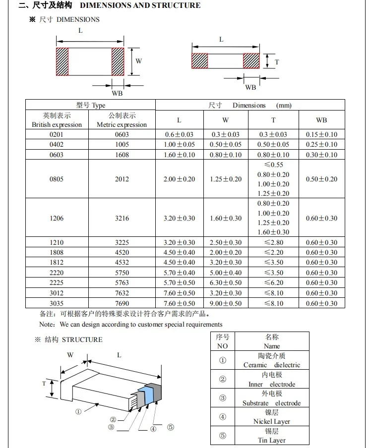
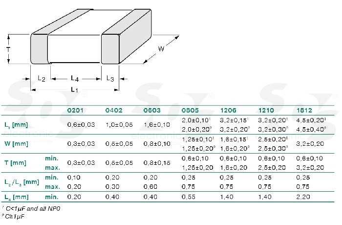
In addition to electrical parameters, the datasheet also encompasses valuable data regarding the physical aspects of the 0.1 uF SMD capacitor. Package dimensions, placement recommendations, and operating temperature range are significant pieces of information to consider.
Package dimensions play a vital role in determining the space requirements for the SMD capacitor on a PCB. Understanding these dimensions helps ensure proper placement and soldering during the assembly process.
The datasheet may also provide recommendations for the ideal placement of the capacitor within a circuit layout. Such guidance can contribute to optimal signal integrity and minimize potential interference, making it crucial to examine and adhere to the manufacturer’s guidelines.
Lastly, the operating temperature range indicates the span of temperatures within which the capacitor can function reliably. This information aids in the selection of capacitors suitable for specific environmental conditions, preventing potential performance issues or failures.
In conclusion, comprehending the 0.1 uF SMD capacitor datasheet involves a thorough understanding of its electrical parameters and physical characteristics. By meticulously examining and interpreting this information, engineers and enthusiasts can confidently select and implement the capacitor in their circuit designs, optimizing the overall performance of their electronic systems.
Decoding the Technical Specifications
In this section, we will delve into the intricacies of deciphering the technical specifications of a commonly used electronic component. By understanding the underlying concepts and principles, you will be able to navigate through the extensive datasheets with ease, making informed decisions about their integration into your electronic projects.
Understanding the Electrical Properties
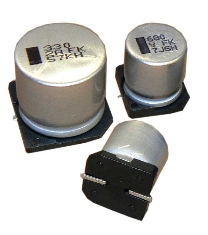
When analyzing the technical specifications of a 0.1 μF Surface Mount Device (SMD) capacitor, it is essential to comprehend the various electrical properties associated with it. These properties provide crucial information about its functionality and performance. Key aspects to consider include capacitance, voltage rating, tolerance, and equivalent series resistance (ESR).
Capacitance: The Storage of Energy
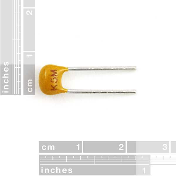
Capacitance, represented in farads (F), is a fundamental parameter that indicates the component’s ability to store electrical energy. It determines the amount of charge a capacitor can hold for a given voltage. In the context of a 0.1 μF SMD capacitor, it signifies its capacity to store a specific amount of charge, enabling the component to contribute to signal filtering, energy storage, and voltage regulation.
Voltage Rating: Safeguarding Your Circuit
Capacitors have a maximum voltage limit beyond which they can become permanently damaged or fail to function optimally. The voltage rating on the datasheet provides valuable insights into the safe operating range for a specific capacitor. By ensuring the voltage rating exceeds the operational voltage in your circuit, you can safeguard your project from potential malfunctions or hazards.
Tolerance: The Margin of Error
Tolerance refers to the acceptable deviation in capacitance from the nominal value. It quantifies the margin of error in the specified capacitance rating for a capacitor. For a 0.1 μF SMD capacitor, the tolerance value gives an indication of the potential variance from the designated capacitance. Understanding this parameter is crucial, particularly when precise values are required in circuit design or performance.
By delving into these technical specifications of a 0.1 μF SMD capacitor, you can unearth valuable insights about its functionality and performance. Armed with this knowledge, you will be better equipped to make informed decisions, ensuring the seamless integration of these electronic components into your projects.