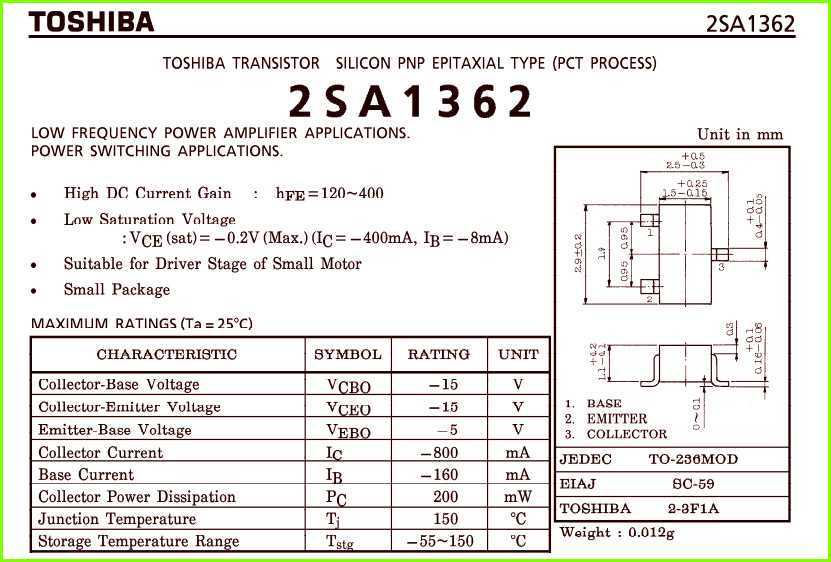
When it comes to exploring the vast world of electronic components, there is one particular item that stands out in terms of its versatility and functionality. This article delves into the intricate details and specifications of the 6228a, a component that has become a cornerstone in various electronic applications.
Without delving into the technical jargon, the 6228a can be best described as a powerful tool that serves as the backbone for many electronic projects. This component not only enhances the performance of electronic devices but also provides a reliable and efficient solution for various tasks.
Revolutionizing the electronic industry, the 6228a offers a multitude of advantages that cater to the ever-evolving needs of technology enthusiasts and professionals alike. Its robust construction ensures durability and longevity, allowing for seamless integration into a wide range of electronic systems.
In a world where efficiency is paramount, the 6228a shines through as a reliable and energy-efficient solution. Equipped with cutting-edge features, this component minimizes power consumption while delivering optimal performance, making it an ideal choice for those seeking both functionality and sustainability in their electronic endeavors.
Stay tuned as we delve deeper into the technical specifications and unique features of the 6228a component, highlighting its role in transforming the landscape of modern electronics.
An Overview of 6228a Datasheet and its Key Features
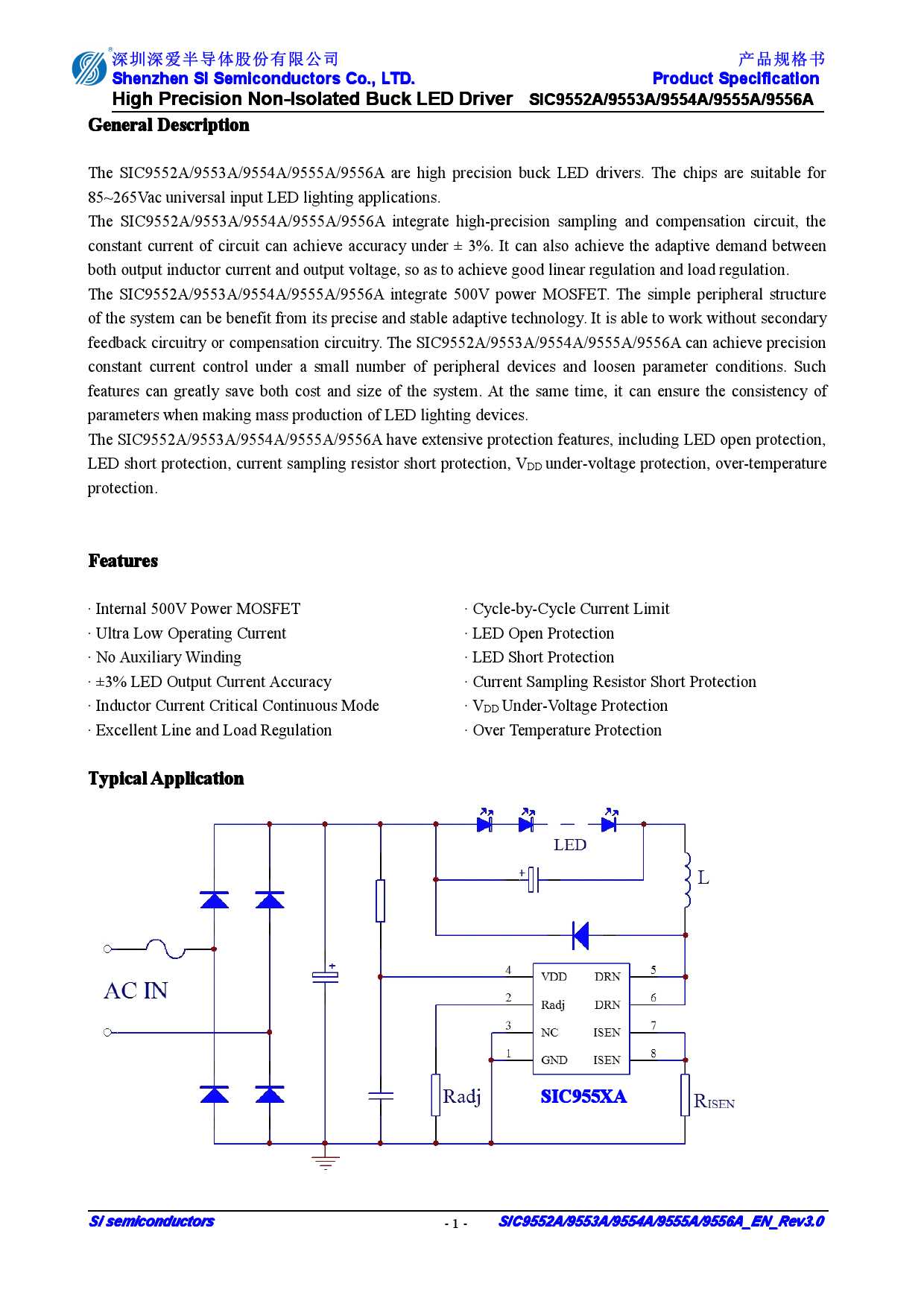
In this section, we will provide an in-depth look at the 6228a datasheet, a comprehensive document that offers valuable information about the features and specifications of the 6228a device. Understanding the key features outlined in the datasheet is crucial for anyone looking to integrate the 6228a into their project or application successfully.
Understanding the Functionality
When delving into the 6228a datasheet, it is essential to grasp the device’s overall functionality. This section will explore the core capabilities and performance of the 6228a, providing readers with a clear understanding of what the device can achieve. From power management to data processing, this section will delve into the intricacies of the 6228a’s operations.
Examining the Key Features
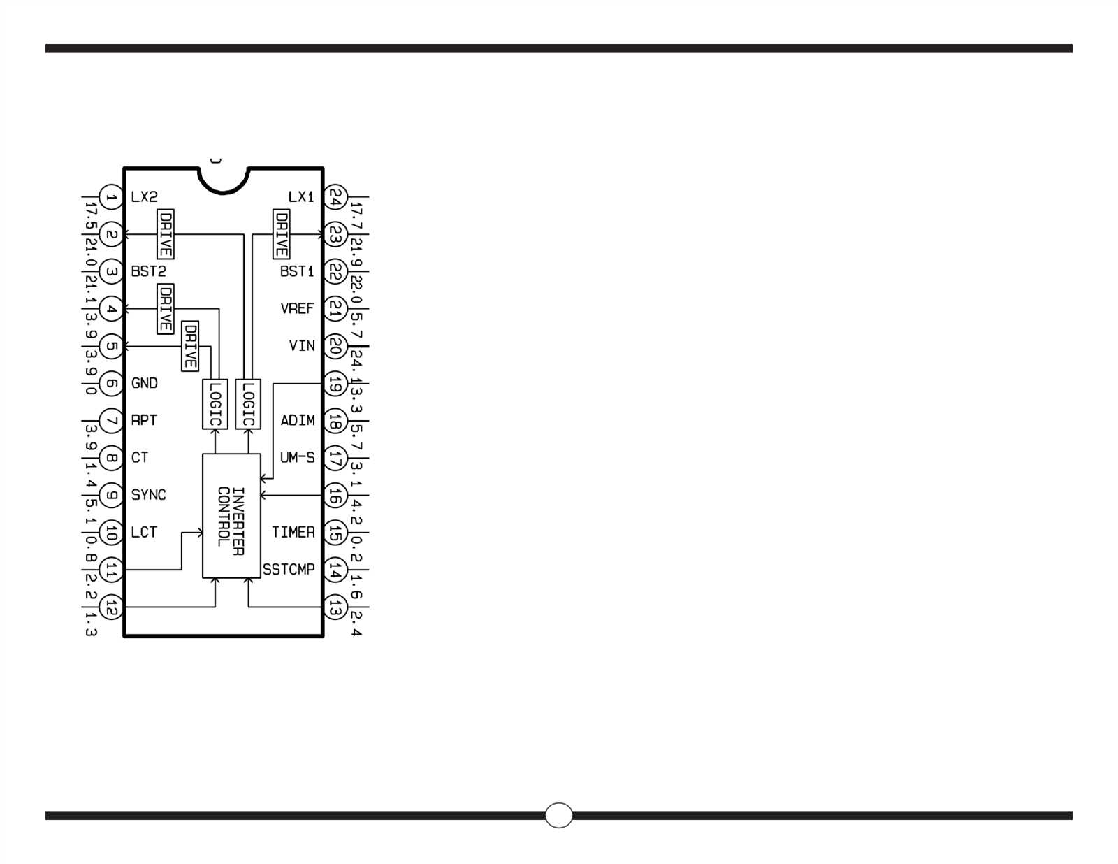
The 6228a boasts a myriad of key features, each playing a vital role in enhancing its performance and versatility. This section of the datasheet will highlight these features, such as the advanced sensor integration capabilities and the seamless connectivity options. Additionally, it will explore the device’s robust security mechanisms and energy-efficient design, ensuring readers understand the unique value proposition offered by the 6228a.
As you delve deeper into the 6228a datasheet, you will gain a comprehensive understanding of the device’s capabilities and how it aligns with your project requirements. Examining the intricacies of the 6228a and its key features will enable you to make informed decisions and harness the full potential of this advanced technology.
Understanding the Technical Specifications of 6228a Datasheet
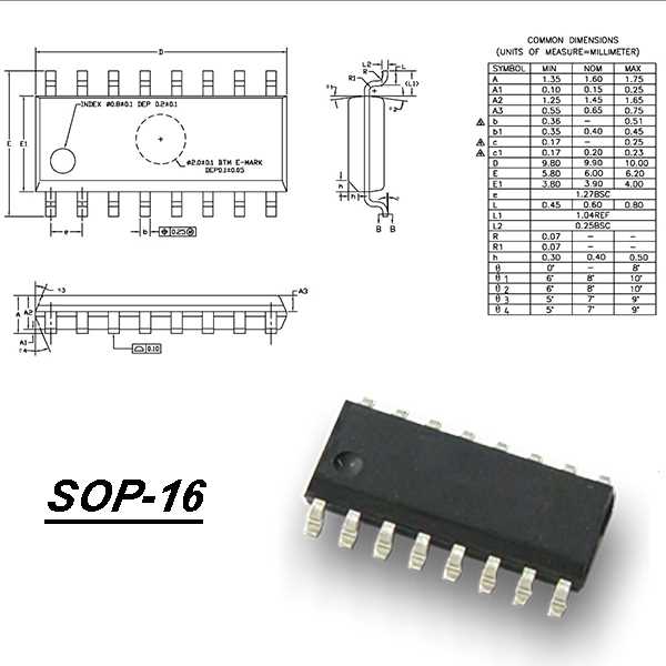
When delving into the technical realm of electronic devices, it is essential to comprehend the various specifications provided in the datasheet. These specifications offer vital insights into the capabilities and functionalities of the 6228a device, enabling users to make informed decisions based on their specific requirements.
One of the key aspects to consider is the input voltage range, which refers to the minimum and maximum voltages that the 6228a device can accept as input. This range determines the compatibility with external power sources and ensures the safe operation of the device. Understanding the input voltage range helps users select the appropriate power supply for reliable and efficient operation.
Another crucial parameter is the output voltage range, which specifies the minimum and maximum voltages that the 6228a device can deliver to external components. This range influences the device’s compatibility with various electrical systems and determines its usefulness in different applications. By comprehending the output voltage range, users can ensure that the device meets the requirements of their specific projects.
The current rating is yet another critical specification that plays a significant role in determining the device’s capability to deliver power to connected components. The current rating identifies the maximum current that the 6228a device can supply, indicating its ability to handle different loads. Understanding the current rating helps users ensure the device can efficiently power their intended circuitry without exceeding its limits.
Additionally, the datasheet provides information on the device’s operating temperature range. This range dictates the environmental conditions within which the 6228a can function reliably. Knowledge of the operating temperature range assists users in selecting suitable thermal management solutions and ensures the device’s longevity and performance under different temperature conditions.
- The safety features and certifications mentioned in the datasheet are of utmost importance to assess the device’s compliance with industry standards and regulations. Understanding these features allows users to determine the device’s suitability for specific applications, guaranteeing enhanced safety and reliability in their projects.
- The datasheet may also highlight the device’s size, weight, and form factor, offering insights into its physical characteristics. Such information aids users in determining whether the 6228a can be easily integrated into their designs, providing convenience and flexibility.
- Furthermore, the performance characteristics, such as response time, accuracy, and stability, are crucial factors to consider. These specifications shed light on the device’s ability to deliver precise and consistent results, ensuring optimal performance in various demanding applications.
- Lastly, the electrical interfaces and communication protocols supported by the 6228a device are essential aspects to explore. Understanding these interfaces enables users to determine compatibility with other components or systems, allowing seamless integration and efficient data transfer.
By comprehending the technical specifications outlined in the 6228a datasheet, users can gain a deeper understanding of the device’s capabilities, limitations, and compatibility with their specific project requirements. This knowledge empowers users to make informed decisions and select the most suitable components for their applications, leading to successful and reliable electronic designs.
An In-depth Analysis of the Performance Parameters and Electrical Characteristics
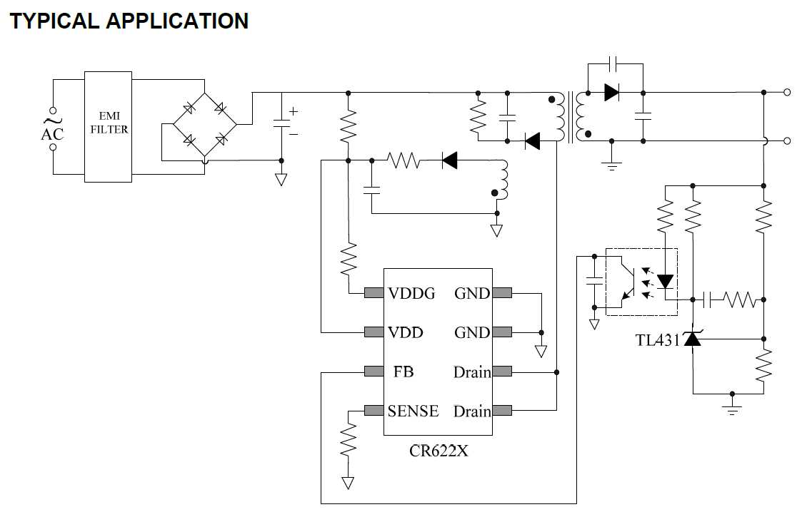
In this section, we will take a detailed look at the various performance parameters and electrical characteristics of the product, providing a comprehensive understanding of its capabilities and functionality. By examining these aspects, we aim to provide valuable insights into the potential use cases and advantages associated with this device, fostering informed decision-making and efficient utilization in various applications.
1. Performance Parameters
- Signal-to-Noise Ratio (SNR): Exploring the relationship between the desired signal and unwanted noise, the SNR plays a crucial role in determining the device’s ability to deliver accurate and high-quality output.
- Gain: Understanding the amplification factor employed by the product enables us to evaluate its ability to enhance weak signals effectively, catering to specific requirements.
- Bandwidth: Investigating the range of frequencies over which the device can operate optimally helps identify its suitability for different data transmission or signal processing tasks.
- Dynamic Range: Assessing the device’s capability to handle different signal strengths without distortion provides insight into its versatility and performance under varying conditions.
2. Electrical Characteristics
- Operating Voltage Range: Examining the range of voltages within which the device can function reliably helps determine its compatibility with different power supply systems.
- Power Consumption: Analyzing the amount of power required by the device facilitates insight into its energy efficiency and long-term cost implications.
- Impedance: Understanding the device’s impedance characteristics aids in matching it with the impedance of connected components, ensuring optimum signal transfer.
- Temperature Range: Investigating the device’s ability to operate within specific temperature limits allows for the identification of suitable operating environments.
By delving into the performance parameters and electrical characteristics, we hope to provide a comprehensive understanding of this product’s capabilities, enabling users to make informed decisions regarding its integration into their systems. The information gathered in this analysis will assist in optimizing the device’s performance, ensuring seamless operation, and maximizing the overall efficiency of the system.
Application Notes and Design Considerations for 6228a Datasheet
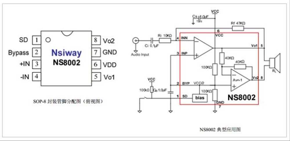
In this section, we will discuss various application notes and design considerations that are crucial for effectively utilizing the features and capabilities of the 6228a device. By examining these considerations, engineers and designers will be able to optimize their circuit designs and incorporate the 6228a seamlessly into their applications.
Firstly, it is important to take into account the power requirements of the 6228a device. Understanding the power consumption characteristics and voltage levels needed for the device to function optimally will allow for proper power management in the overall design. Additionally, considering power supply noise and stability is essential to prevent any voltage fluctuations that could potentially affect the performance of the device.
Furthermore, the physical layout and printed circuit board (PCB) design play a crucial role in the overall performance of the 6228a device. Proper grounding techniques, signal routing, and component placement should be carefully considered to minimize noise and interference. This includes utilizing ground planes, separating analog and digital signals, and minimizing the length of high-speed signal traces.
Another important aspect to consider is the thermal management of the 6228a device. Understanding the thermal characteristics and heat dissipation requirements of the device will aid in selecting appropriate heat sinks, thermal pads, or other cooling mechanisms. Proper thermal management ensures the device remains within its specified temperature range, avoiding any performance degradation or potential damage.
Additionally, it is crucial to consider the electromagnetic compatibility (EMC) requirements when designing with the 6228a. By adhering to best practices for EMC, such as proper shielding, filtering, and grounding, engineers can ensure that the device operates reliably in the intended environment and does not interfere with other neighboring devices.
Lastly, during the design process, it is essential to thoroughly review the datasheet for the 6228a device, paying close attention to the device’s specifications, timing diagrams, and recommended operating conditions. This comprehensive understanding will provide valuable insights into the device’s capabilities, limitations, and potential design trade-offs.
- Consider power requirements and management
- Optimize physical layout and PCB design
- Implement effective thermal management
- Adhere to electromagnetic compatibility (EMC) requirements
- Thoroughly review the datasheet for complete understanding
By considering these application notes and design considerations, engineers and designers can ensure successful integration of the 6228a device into their circuits, maximizing its performance and functionality.
Guidelines for Effective Implementation and Integration in Various Electronic Systems
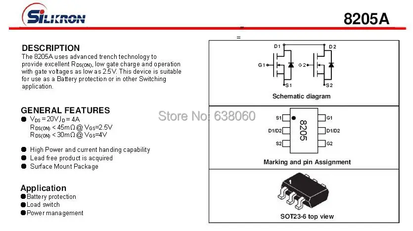
In the ever-evolving landscape of electronic systems, successful implementation and integration are crucial for ensuring optimal performance and functionality. This article discusses a set of guidelines that can help engineers and designers effectively navigate the complexities of integrating electronic components and systems into a wide range of applications.
1. Understand the System Requirements: Before embarking on any integration process, it is essential to have a comprehensive understanding of the specific requirements of the electronic system. This includes factors such as power consumption, size constraints, operational environment, and functionality expectations. By having a clear understanding of the system requirements, engineers can make informed decisions regarding the selection and integration of components.
2. Consider Compatibility: When integrating electronic components into a system, compatibility is of utmost importance. It involves ensuring that all components, subsystems, and interfaces work harmoniously together without issues such as conflicting protocols or voltage levels. Conducting thorough compatibility tests and utilizing industry-standard interfaces will help in avoiding potential integration challenges.
3. Embrace Modularity: Modular design and implementation can greatly simplify the integration process and enhance the scalability and flexibility of electronic systems. By breaking down complex systems into smaller, independently functioning modules, engineers can easily replace or upgrade components without affecting the overall functionality. Utilizing standardized interface protocols and modular connectors can further facilitate seamless integration.
4. Pay Attention to Signal Integrity: Maintaining signal integrity is crucial for preserving the integrity of the electronic system. The integration process should account for factors such as signal loss, noise, and electromagnetic interference. Proper grounding, shielding, and routing techniques should be employed to mitigate these issues and ensure optimal signal transmission and reception.
5. Perform Thorough Testing: Before deployment, rigorous testing should be conducted to validate the integration of electronic components and verify the performance of the overall system. This includes functional testing, stress testing, and compatibility testing. Identifying and rectifying any integration issues during the testing phase will minimize the risk of failures or malfunctions in real-world applications.
6. Continuously Monitor and Improve: Integration is an ongoing process, and it is essential to monitor the performance of electronic systems post-implementation. Regular maintenance, updates, and monitoring of system performance can help identify areas for improvement and ensure that the integrated system operates optimally throughout its lifecycle.
By following these guidelines, engineers and designers can effectively implement and integrate electronic systems into a wide array of applications, optimizing performance, functionality, and reliability.