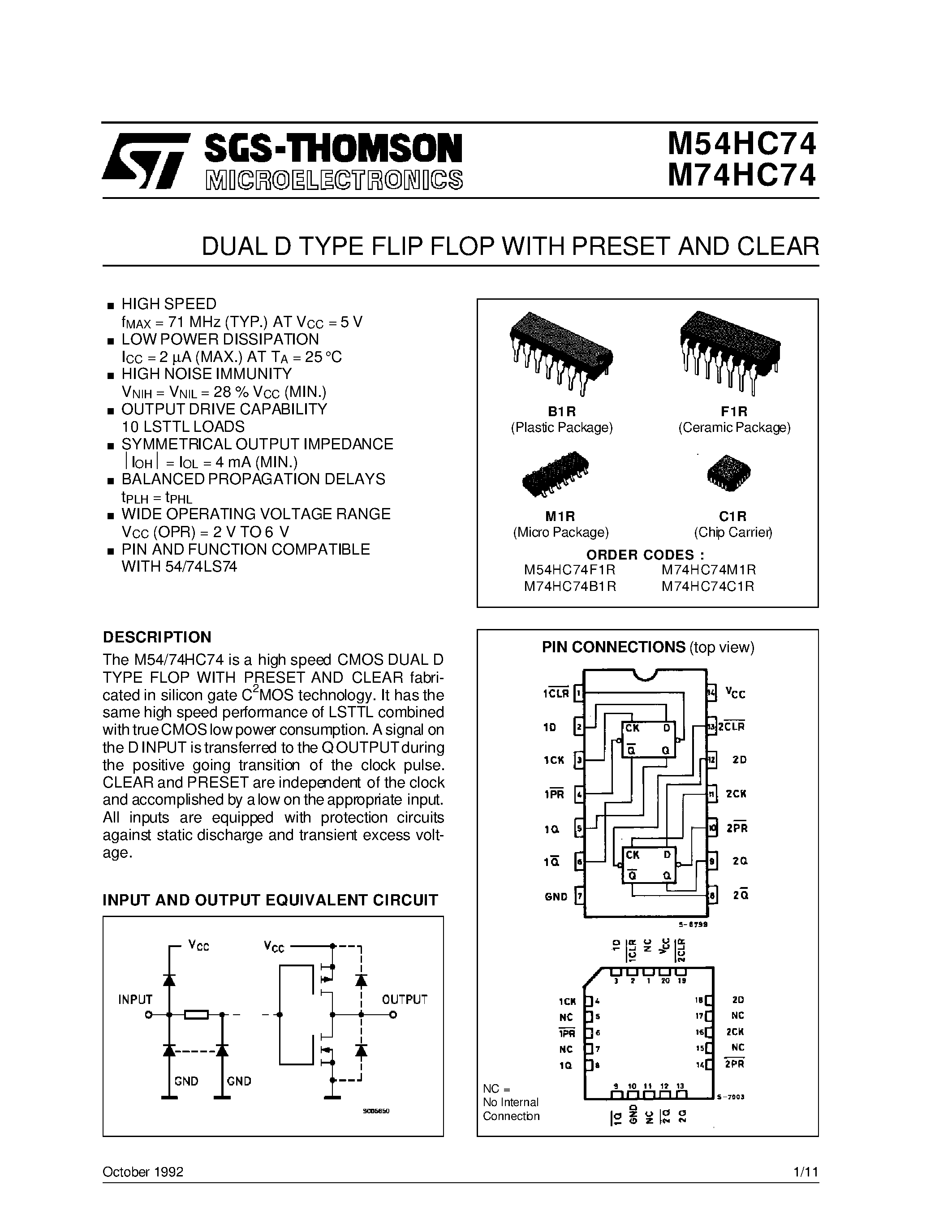
Are you fascinated by the intricate workings of electronic devices? Do you revel in the excitement of discovering new components and exploring their capabilities? If so, then prepare to embark on a journey into the realm of 74 74 datasheets – a treasure trove of information that will unlock the secrets behind these powerful integrated circuits.
In this article, we will delve into the realm of 74 74 datasheets, also known as .pdf and electronics device descriptions, and explore the myriad of possibilities they offer to electronics enthusiasts and professionals alike. From their origins to their applications, we will examine the inner workings of these powerful components and the wealth of knowledge they contain.
Furthermore, we will shed light on the significance of 74 74 datasheets in the field of electronics. These documents serve as essential guides, providing engineers and hobbyists with a comprehensive understanding of the component’s functionality, pin configurations, electrical characteristics, and much more. With every bit of data meticulously outlined, 74 74 datasheets offer a road map to success in circuit design and implementation.
So, join us as we unravel the enigmatic world of 74 74 datasheets, exploring the depths of their information and discovering the incredible possibilities they hold. Prepare to be amazed by the sheer comprehensiveness and wealth of knowledge contained within these technical documents. Whether you are an aspiring engineer or a curious hobbyist, this article will provide you with the insight and understanding needed to unlock the full potential of 74 74 datasheets.
Understanding the 74 74 Datasheet: Key Specifications and Features
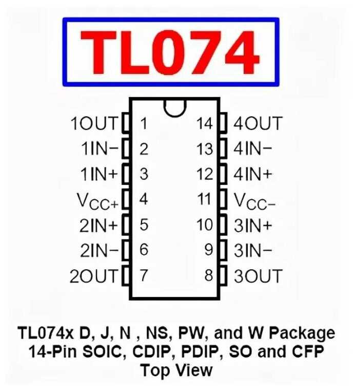
In the following section, we will provide an overview of the important specifications and features of the 74 74, commonly referred to as the “dual positive-edge triggered D-type flip-flop”. This component is widely used in digital electronic circuits for its ability to store binary information and perform various logic functions.
Functional Description
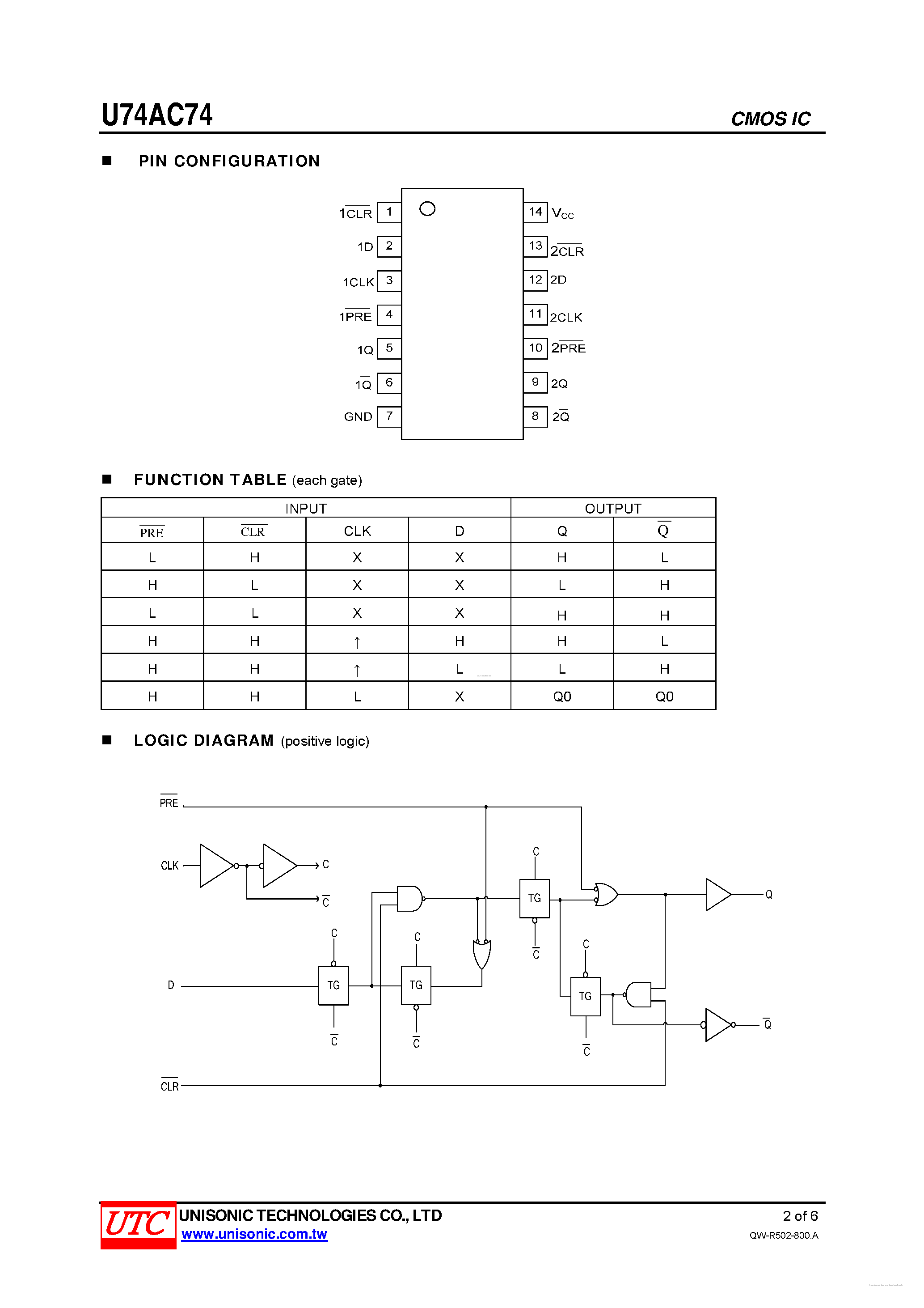
At its core, the 74 74 is designed to store a single bit of digital information. It consists of two identical flip-flops, each with an independent data input, clock input, set input, and reset input. The flip-flops provide a means of storing and preserving a binary value until it is updated by a clock signal. When the clock signal transitions from low to high, the current value at the data input is transferred to the outputs of the flip-flops. This transfer of data occurs simultaneously for both flip-flops, resulting in a synchronized update.
Key Specifications
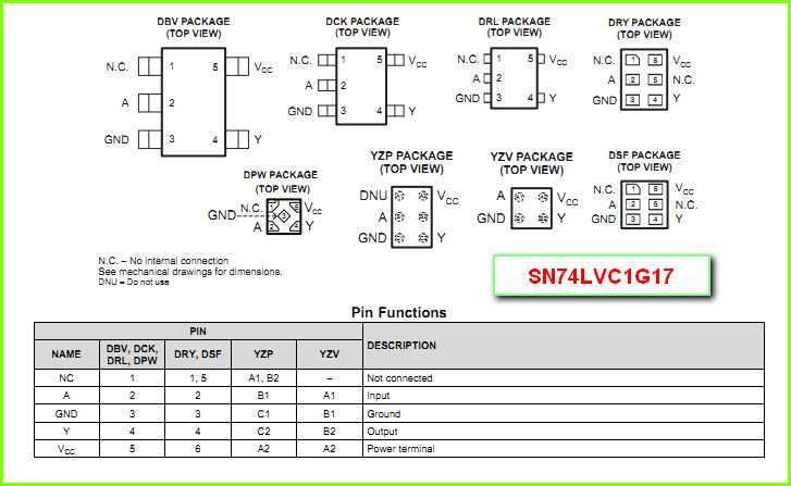
- Voltage: The 74 74 operates within a specific voltage range, typically between 4.5 volts and 5.5 volts, ensuring compatibility with common digital systems.
- Current Consumption: The component has a low current consumption of around 2mA, making it suitable for power-sensitive applications.
- Propagation Delay: The propagation delay is the time it takes for the input signal to propagate through the flip-flop circuitry and appear at the output. The 74 74 has a short propagation delay, typically in the range of a few nanoseconds.
- Maximum Clock Frequency: This specification defines the maximum speed at which the flip-flops can operate reliably. The 74 74 can typically handle clock frequencies up to several hundred megahertz.
- Output Drive Capability: The component has a specified output drive capability, which refers to its ability to provide sufficient current to drive connected circuitry without distortion or significant voltage drop.
These key specifications illustrate the performance characteristics and limitations of the 74 74, enabling designers to assess its suitability for a given application.
In conclusion, understanding the specifications and features of the 74 74 is crucial for successful integration into digital electronic circuits. By evaluating its voltage range, current consumption, propagation delay, maximum clock frequency, and output drive capability, engineers can make informed decisions regarding its application in various projects.
An Overview of the 74 74 Integrated Circuit
The 74 74 integrated circuit is a versatile electronic component that plays a crucial role in various electronic devices. This article provides an overview of the 74 74 IC, highlighting its key features, applications, and benefits.
Understanding the 74 74 Integrated Circuit
The 74 74 IC is a widely used integrated circuit in the field of electronics. It is known for its reliability, compact size, and high performance capabilities. This IC consists of multiple electronic components, such as transistors, resistors, and capacitors, integrated onto a single chip.
The 74 74 IC operates by receiving, processing, and transferring electrical signals. It has the ability to perform various logical operations, making it a fundamental building block for digital circuits. With its multiple inputs and outputs, this IC can manipulate binary information, enabling the creation of complex electronic systems.
Applications of the 74 74 Integrated Circuit
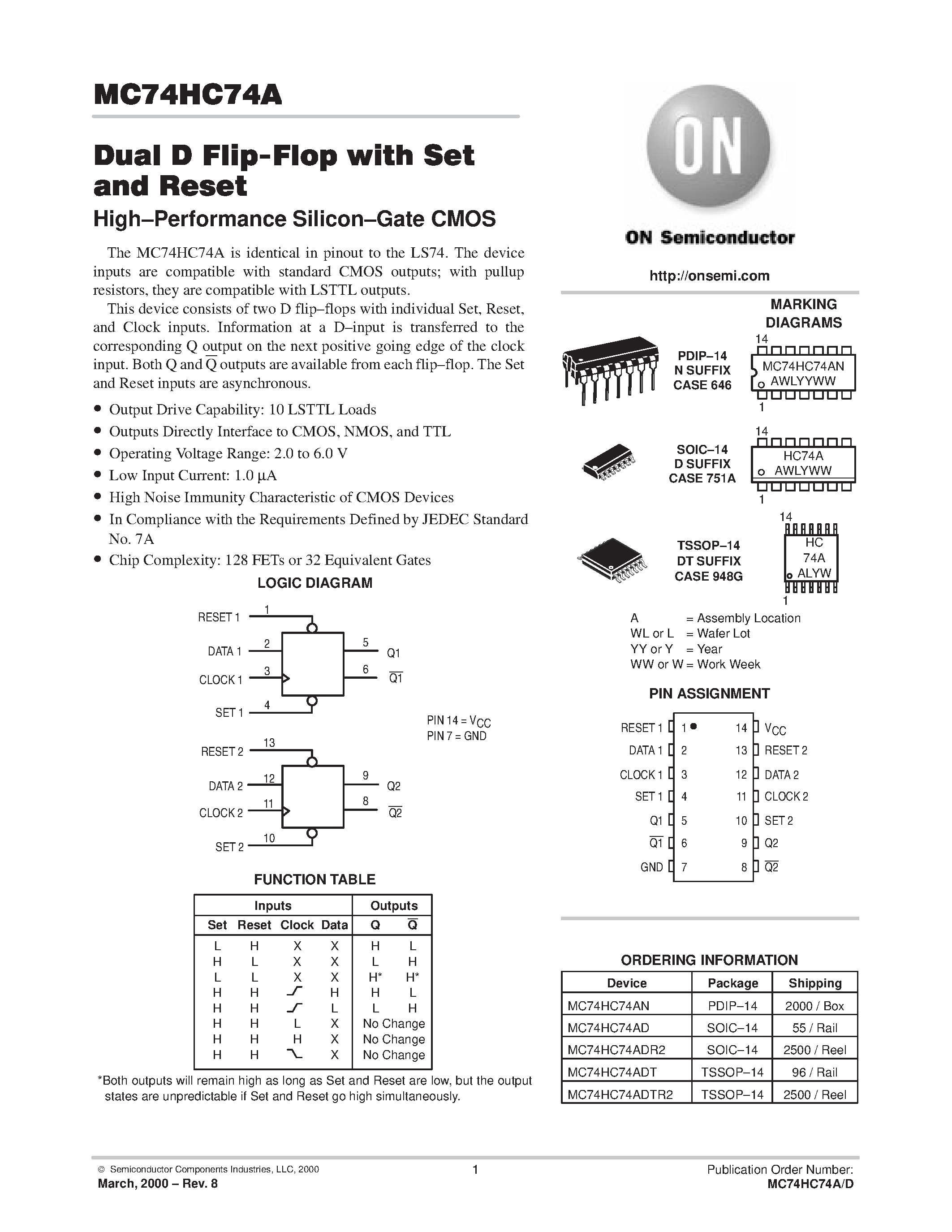
The versatility of the 74 74 IC makes it suitable for a wide range of applications in the electronics industry. It is commonly used in digital systems, such as computers, calculators, and microcontrollers, where it performs tasks like data storage, signal amplification, and logical operations.
In addition, the 74 74 IC finds applications in communication systems, serving as a key component in data transmission and reception. Its ability to process and manipulate signals accurately makes it a vital part of devices like modems, routers, and telecommunication equipment.
Beyond digital electronics, the 74 74 IC is also utilized in automotive systems, aerospace technologies, and industrial automation. Its reliability and durability make it suitable for harsh operating conditions, ensuring stable and efficient performance in challenging environments.
In summary, the 74 74 integrated circuit is a versatile and essential component in modern electronics. Its capacity to perform various logical operations and its widespread use in different industries make it a significant building block for numerous electronic devices and systems.
Key Specifications to Consider
When considering the 74 74 device, it is important to take into account several key specifications that greatly impact its performance. These specifications provide valuable information about the device’s capabilities and can guide you in making informed decisions.
1. Speed: The speed specification refers to the device’s operating frequency or how quickly it can process data. It determines how fast the device can respond to input signals and perform the desired functions. Consider the speed requirements of your specific application to ensure the device can handle the necessary tasks efficiently.
2. Power Consumption: Another crucial specification to consider is the device’s power consumption. This determines the amount of power required for the device to operate correctly. Assessing the power consumption is essential, as it directly impacts the overall energy efficiency and longevity of the device. Lower power consumption is generally preferable, as it helps reduce costs and extends battery life in mobile applications.
3. Voltage Tolerance: The voltage tolerance specification indicates the range of acceptable input voltage levels that the device can handle without experiencing damage. It is crucial to ensure that the device can withstand the voltage levels present in your specific application. Failing to do so may result in overheating or permanent damage to the device.
4. Operating Temperature Range: The operating temperature range specifies the temperatures within which the device can function reliably. Different applications may expose the device to varying temperature conditions, and it is essential to verify that the device can operate within those parameters without compromising its performance or lifespan.
5. Package Type: The package type refers to the physical encapsulation of the device. It is important to consider the package type as it determines compatibility with your intended application and the ease of integrating the device into your design. Common package types include DIP (Dual Inline Package), SOP (Small Outline Package), and BGA (Ball Grid Array).
6. Pin Configuration: The pin configuration specifies the layout and arrangement of the device’s pins. Understanding the pin configuration is crucial for proper connection and interfacing with other components or devices in your application. This specification ensures seamless integration and guarantees the device functions as intended within your overall system.
7. Additional Features: Lastly, consider any additional features or functionalities that the 74 74 device may offer. These could include built-in protections, communication protocols, or specialized operating modes that enhance the device’s functionality and make it suitable for specific applications or industries.
By thoroughly evaluating these key specifications, you can make an informed decision and select the 74 74 device that best meets the requirements of your application, ensuring optimal performance, compatibility, and reliability.
Notable Features of the 74 74 Datasheet
The 74 74 datasheet stands out due to its exceptional characteristics, which set it apart from other similar documents. This article will highlight some of the noteworthy aspects of this datasheet, providing valuable information to those seeking to understand its contents thoroughly.
- Comprehensive Overview: The 74 74 datasheet offers a comprehensive overview of the device it represents, providing a detailed description of its main functionality and applications. It presents the device in a clear and concise manner, making it easier for users to grasp its purpose and potential uses.
- Technical Specifications: One of the key features of the 74 74 datasheet is its inclusion of essential technical specifications. These specifications outline the device’s electrical characteristics, such as voltage ratings, power consumption, and input/output logic levels. They enable engineers and designers to make informed decisions about the device’s integration into their projects.
- Functional Diagrams: To enhance understanding, the 74 74 datasheet includes functional diagrams that illustrate the internal structure and operation of the device. These visual representations aid in visualizing the flow of data and signals within the component, facilitating the design process and troubleshooting.
- Pin Configuration: Another notable feature of the 74 74 datasheet is the detailed pin configuration table. This table provides a clear and organized layout of the device’s pins, each labeled with its corresponding function. Such information is crucial for properly connecting the device within a circuit or system.
- Timing Diagrams: The inclusion of timing diagrams in the 74 74 datasheet plays a crucial role in understanding the device’s timing characteristics. These diagrams illustrate the timing relationships between input and output signals, allowing designers to accurately determine signal propagation delays and ensure proper operation.
- Application Examples: To demonstrate the versatility of the 74 74, the datasheet includes application examples that showcase potential use cases and circuit configurations. These examples serve as valuable references for engineers, providing inspiration and guidance for designing their own circuits.
Overall, the 74 74 datasheet sets itself apart with its comprehensive overview, detailed technical specifications, visual representations, pin configuration details, timing diagrams, and practical application examples. By providing such a wealth of information, it equips users with the necessary knowledge to integrate and utilize this device effectively in their electronic designs.


