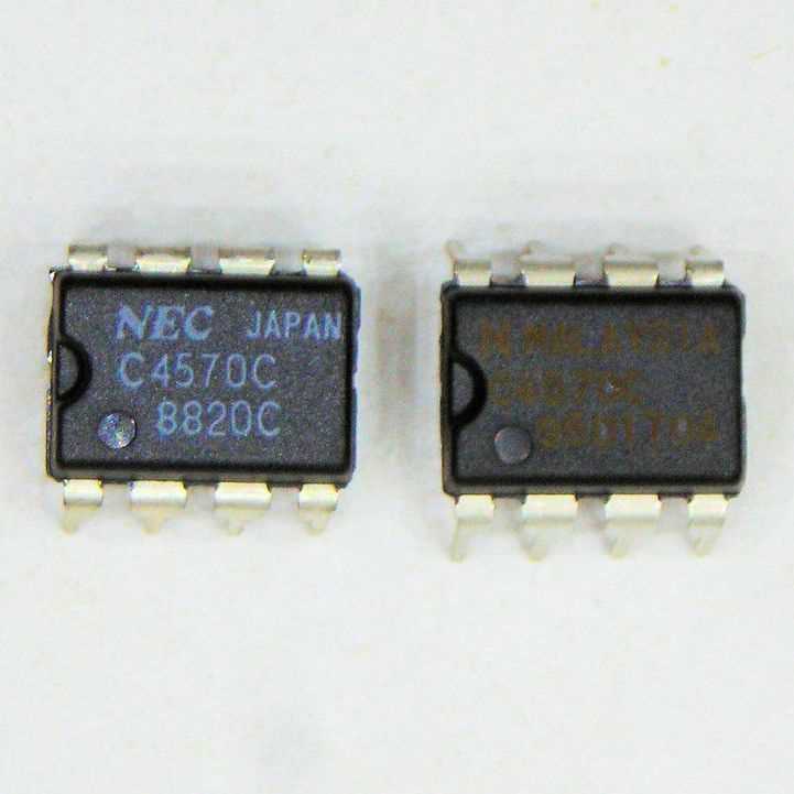
Since its inception, the field of electronics has seen remarkable advancements, with each new innovation pushing the boundaries of what was previously thought possible. One such breakthrough in this ever-evolving landscape is the C4570c integrated circuit. Designed to revolutionize electronic systems, this remarkable marvel offers unparalleled functionality and efficiency.
Beyond its technical specifications, the C4570c represents a leap forward in the world of integrated circuits. With its meticulously designed architecture and exceptional performance, this state-of-the-art component seamlessly integrates into a wide range of electronic applications. Its versatility knows no bounds, allowing engineers and hobbyists alike to unlock creative possibilities previously unattainable.
The heart of the C4570c lies in its ability to enhance signal processing, amplification, and modulation, rendering it an indispensable tool in the realm of electronic circuitry. By leveraging its exceptional signal-to-noise ratio and low distortion characteristics, the C4570c empowers engineers to achieve high-fidelity output and accurate audio reproduction. Whether it be in professional audio systems, home entertainment setups, or even medical devices, the C4570c guarantees an unparalleled sonic experience.
Understanding the C4570c Datasheet: An Overview of Key Specifications
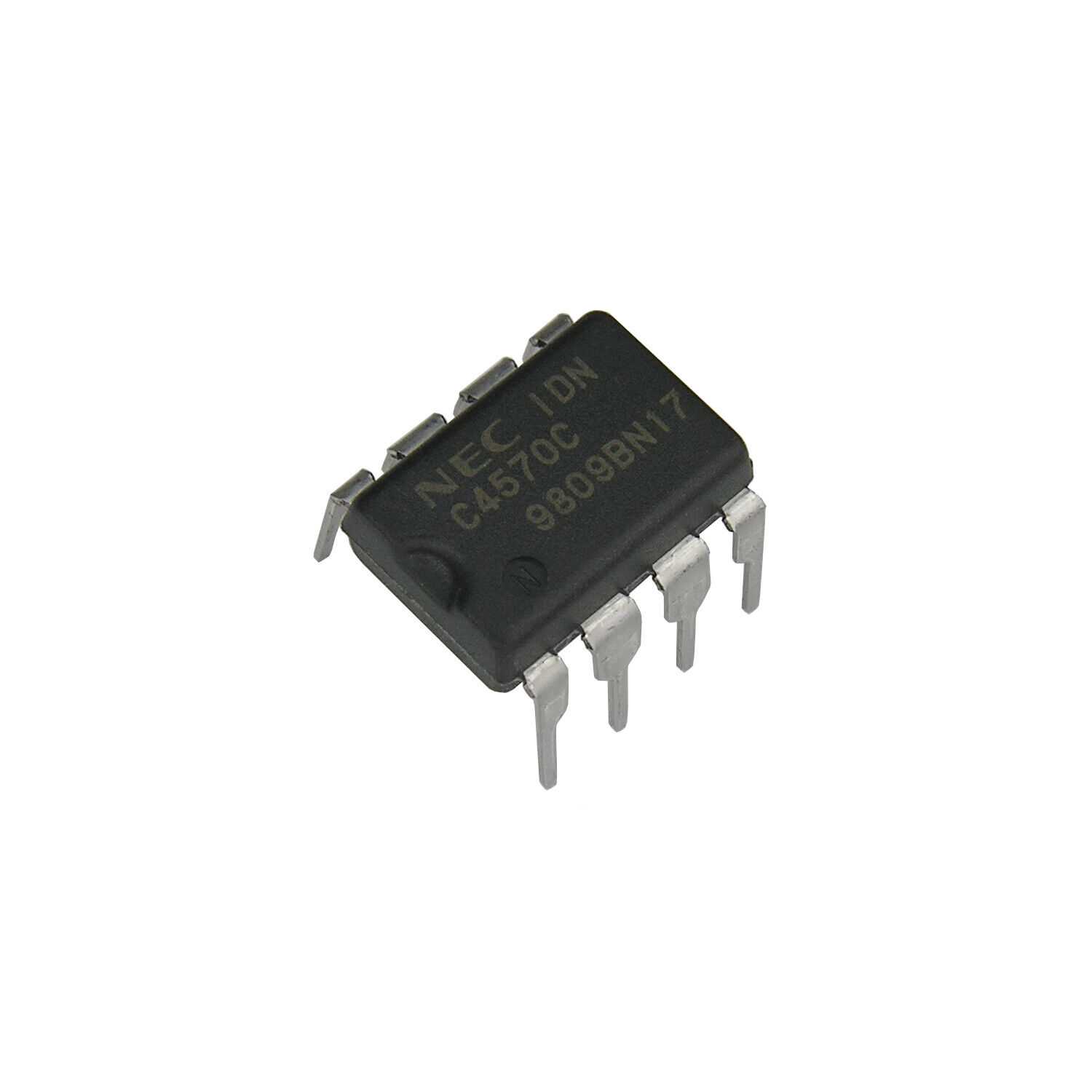
When exploring the details of electronic components, it is essential to analyze the datasheet to fully comprehend their capabilities and characteristics. In this section, we will provide an overview of the important specifications of the C4570c, enabling a better understanding of its potential applications and limitations.
| Specification | Description |
|---|---|
| Supply Voltage | The supply voltage refers to the range of voltage that can be safely provided to the C4570c. It is crucial to stay within this range to ensure optimal performance and prevent damage. |
| Input Bias Current | The input bias current is the amount of current that enters the input stage of the C4570c. It is a critical specification to consider, as it can impact the accuracy and stability of the device. |
| Output Power | The output power of the C4570c determines the maximum amount of power that the device can deliver to the load. It plays a significant role in determining the suitability of the component for specific applications. |
| Input Voltage Range | The input voltage range specifies the range of voltages that can be applied to the inputs of the C4570c. Understanding this specification is crucial in ensuring proper signal compatibility and avoiding distortion or damage. |
| Operating Temperature | The operating temperature range indicates the ambient temperature range in which the C4570c can safely operate. It is essential to adhere to this specification to maintain the longevity and reliability of the component. |
By familiarizing ourselves with the key specifications of the C4570c, we gain insights into its capabilities and limitations. This knowledge empowers engineers and enthusiasts to make informed decisions regarding the implementation of the C4570c in various electronic circuits and projects.
Pin Configuration and Functionality
In this section, we will explore the pin configuration and functionality of a certain electronic component, providing an overview of its connections and the role each pin plays in its operation.
Pinout Diagram
The pinout diagram below illustrates the arrangement of pins on the component. It showcases the physical structure of the component and provides a visual reference for understanding its connectivity.
| Pin Name | Description |
|---|---|
| Pin 1 | This pin serves an important role in the component, providing a specific function related to its operation. The pin may be connected to other components or external circuits in order to enable certain capabilities or features. |
| Pin 2 | The functionality of this pin is crucial for the proper functioning of the component. It may be responsible for input or output signals, or it could serve as a reference or ground connection. |
| Pin 3 | This pin plays a significant role in the overall functionality of the component. It may be involved in controlling certain aspects of its operation or facilitating the transfer of information between different parts of the circuit. |
| Pin 4 | This pin has a specific purpose, which helps in achieving the desired functionality of the component. It might be associated with power supply, data transfer, or some other important aspect necessary for its operation. |
Pin Functionality
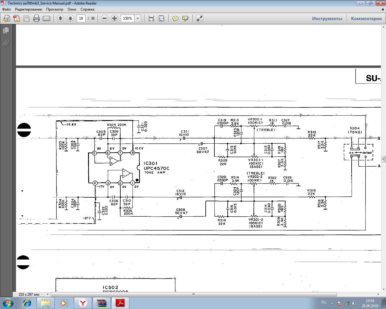
The pins of the component have distinct functionalities that are critical for its operation. By understanding the purpose of each pin, engineers and technicians can effectively utilize the component in their respective applications.
Pin 1, for example, is responsible for a specific function such as signal processing or voltage regulation. It may need to be connected to an external circuit to perform its intended role successfully.
On the other hand, pin 2 serves as an essential input/output connection, allowing the component to receive or transmit signals to other components or subsystems. Its functionality could be further enhanced by connecting it to complementary pins or using it in conjunction with other components.
Pin 3 plays a crucial role in controlling the behavior of the component. Its connection to certain input or output lines helps in regulating the overall functionality or allowing communication between different parts of the circuit.
Lastly, pin 4 is specifically dedicated to a particular function, which could be related to power supply, communication protocols, or data transfer. Understanding its role is essential to ensure the correct operation of the component and its compatibility with the overall system.
By comprehending the pin configuration and functionality of a component, engineers can harness its capabilities effectively and integrate it into their electronic designs, enabling the creation of innovative and efficient systems.
Electrical Characteristics and Performance Parameters
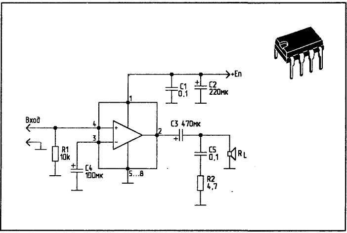
In this section, we will explore the electrical characteristics and performance parameters of the C4570c integrated circuit. Understanding these specifications is crucial for designing and using the circuit effectively. These parameters provide valuable insights into the behavior and capability of the C4570c, allowing engineers to optimize its performance in various applications.
1. Supply Voltage and Current
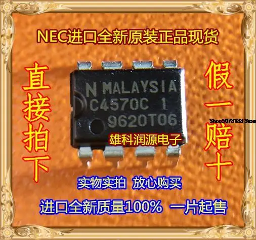
The C4570c operates within a specified supply voltage range, which ensures its proper functioning. It is important to accurately provide the required voltage to avoid any potential malfunctions or damage to the circuit. Additionally, understanding the current consumption of the C4570c helps in determining the power requirements for the overall system.
2. Input and Output Characteristics
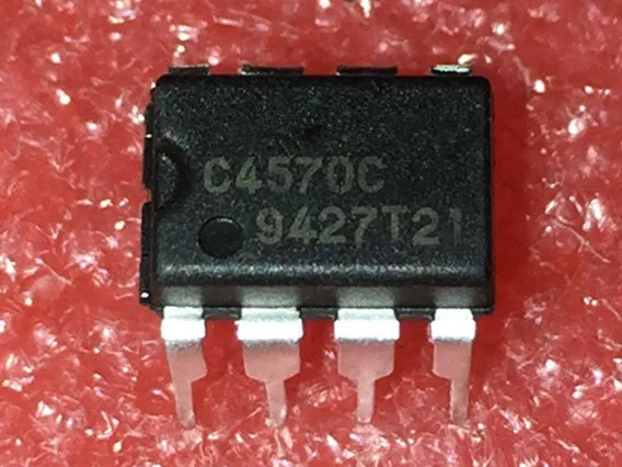
The input characteristics of the C4570c provide information about the voltage levels and impedance requirements for the input signals. This helps in designing appropriate signal conditioning and interfacing circuits. On the other hand, the output characteristics describe the voltage levels, current capabilities, and impedance of the C4570c’s output signals.
The signal-to-noise ratio (SNR), total harmonic distortion (THD), and frequency response are additional important performance parameters. These specifications define the quality of the analog signal being processed by the C4570c, and they determine the accuracy and fidelity of the output signals.
3. Gain and Bandwidth
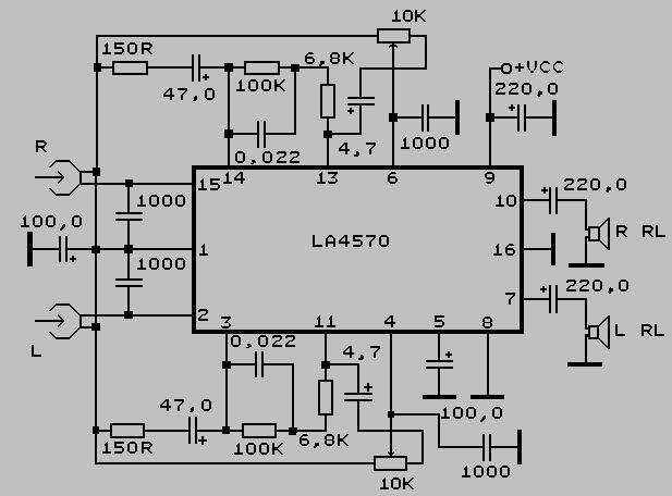
The C4570c has a specified gain value, which indicates the amplification factor it provides for the input signals. This parameter is essential for determining the signal level required at the input to achieve the desired output level. The bandwidth specification of the C4570c defines the range of frequencies within which the circuit can accurately amplify or process the input signals.
Furthermore, the input and output impedance of the C4570c impact the overall performance of the circuit. Understanding these parameters helps in proper impedance matching to ensure efficient signal transfer and prevent signal degradation.
By carefully analyzing and considering these electrical characteristics and performance parameters, engineers can make informed decisions regarding the utilization of the C4570c integrated circuit. These specifications serve as a foundation for achieving optimum performance and reliability in various applications.
Application Circuit Design and Best Practices
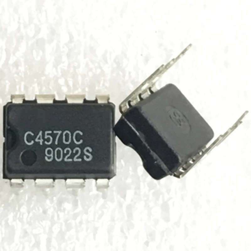
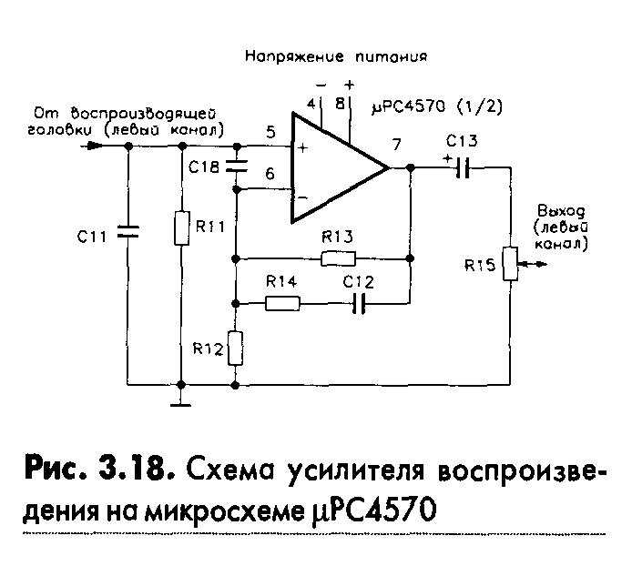
In this section, we will discuss the principles and guidelines for designing an application circuit using the C4570c integrated circuit. By following these best practices, you can maximize the performance and reliability of your circuit while ensuring the optimal operation of the C4570c.
Understanding the Application Circuit
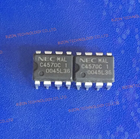
Before diving into the design process, it is crucial to have a clear understanding of the application circuit’s purpose and the desired outcomes. By defining the circuit’s objectives, you can identify the specific requirements and constraints that will shape your design choices.
Additionally, it is important to consider the intended application environment and the potential challenges it may present. Factors such as temperature, noise, and power supply stability can significantly impact circuit performance, and must be taken into account during the design phase.
Component Selection and Layout
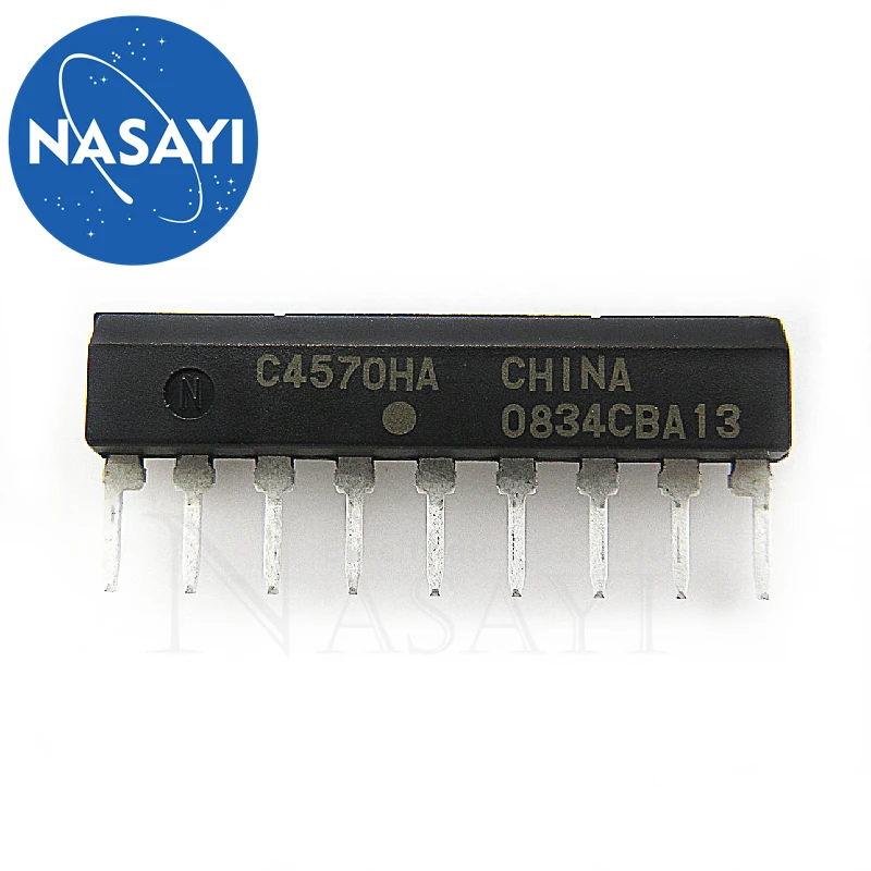
When selecting components, it is essential to choose those that are compatible with the specifications and requirements of the C4570c. Pay attention to parameters such as voltage ratings, current limits, and frequency response to ensure seamless integration and optimal performance.
Furthermore, thoughtful component layout is critical to minimize interference and optimize signal flow. Proper placement of decoupling capacitors, grounding techniques, and signal routing can significantly reduce noise and cross-talk, enhancing overall circuit performance.
It is also advisable to consider the thermal properties of the components and the associated heat dissipation. Adequate heat sinks and thermal management techniques should be incorporated into the circuit design to prevent overheating and ensure long-term reliability.
Power Supply and Signal Integrity
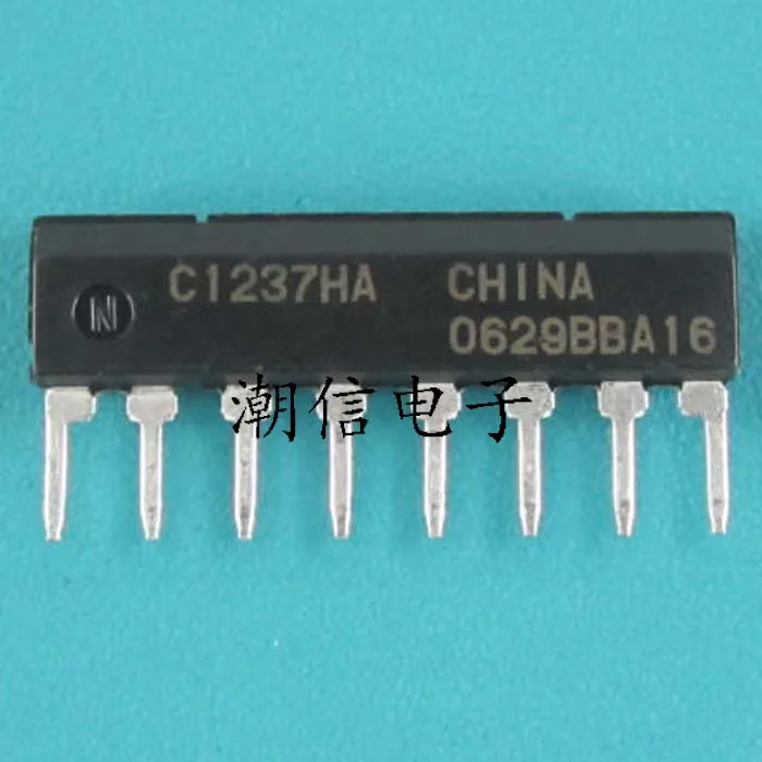
The stability and cleanliness of the power supply directly impact the performance of the C4570c and the overall circuit. It is recommended to use a well-regulated power supply with low ripple and noise levels to guarantee reliable operation and prevent unwanted distortions or malfunctions.
Signal integrity is another crucial aspect to consider when designing the application circuit. Pay attention to impedance mismatches, signal attenuation, and electromagnetic interference (EMI). Proper shielding, impedance matching techniques, and signal conditioning can help preserve signal integrity and enhance the circuit’s robustness.
By following these design principles and best practices, you can ensure the successful implementation of the C4570c in your application circuit, achieving optimal performance, reliability, and longevity.