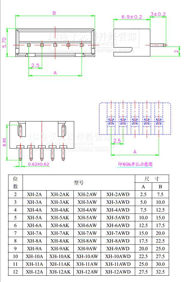
Embarking on a journey through technical specifications invites a nuanced exploration of elemental connectivity. Within the intricate fabric of electronic assemblages, lies a fundamental nexus awaiting decipherment. Diving into the realm of schematic intricacies, one encounters a realm where abstraction meets precision, where essence transcends the mere sum of its parts.
Delving into the heart of information repositories, one discerns a lexicon of intricately interwoven concepts awaiting elucidation. These documents serve as cartographic guides through the labyrinth of circuitry, offering glimpses into the inner workings of our digital world. Unraveling the enigma of binary communication necessitates a meticulous decoding of technical vernacular, where every term holds significance in the grand tapestry of connectivity.
Peering into the annals of engineering discourse, one encounters a symphony of descriptors harmonizing to compose a symmetrical portrait of functionality. Amidst this semantic orchestra, lies a segment dedicated to the delineation of a humble duo: a pair of conductive pathways embodying the essence of electrical interconnectivity. Within these pages, the narrative unfolds, revealing the intricate dance of electrons within the confines of two discrete conduits.
The Basics of 2-Pin Connection Blueprint
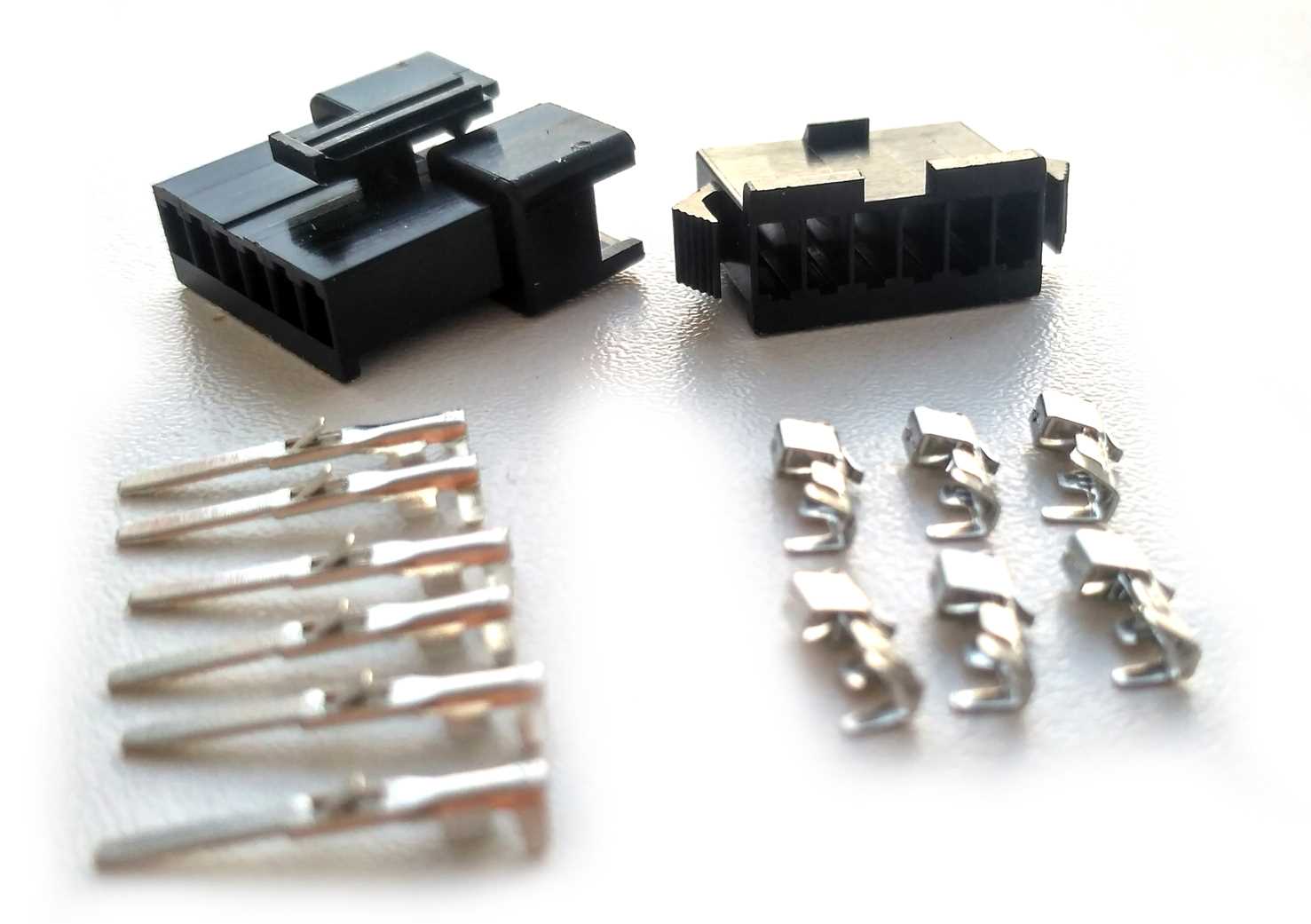
In the realm of electronic components, understanding the fundamental blueprint of a 2-pin connection is paramount. This section delves into the foundational aspects of deciphering and comprehending the intricate details presented in a standard 2-pin connection blueprint.
Deciphering the Schematic Overview
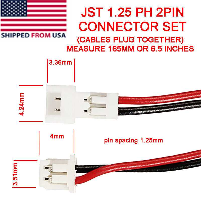
When exploring the schematic overview of a 2-pin connection, it’s essential to grasp the symbolic representation of each element depicted. This involves interpreting the various symbols, lines, and annotations that collectively outline the connectivity and functionality of the components involved.
Interpreting Electrical Specifications
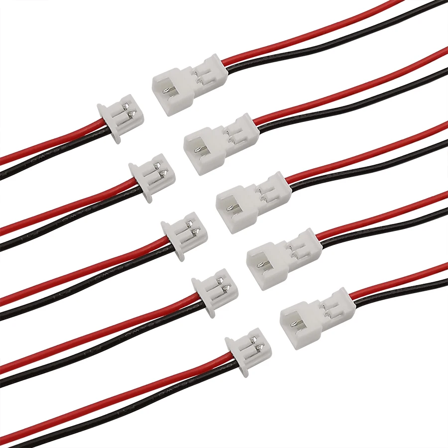
Electrical specifications elucidate crucial details regarding voltage, current, resistance, and other pertinent parameters relevant to the 2-pin connection. By interpreting these specifications, one can gain insights into the operational limits and compatibility requirements of the connector, facilitating informed decision-making in electronic design and assembly.
Understanding Pin Configuration and Orientation
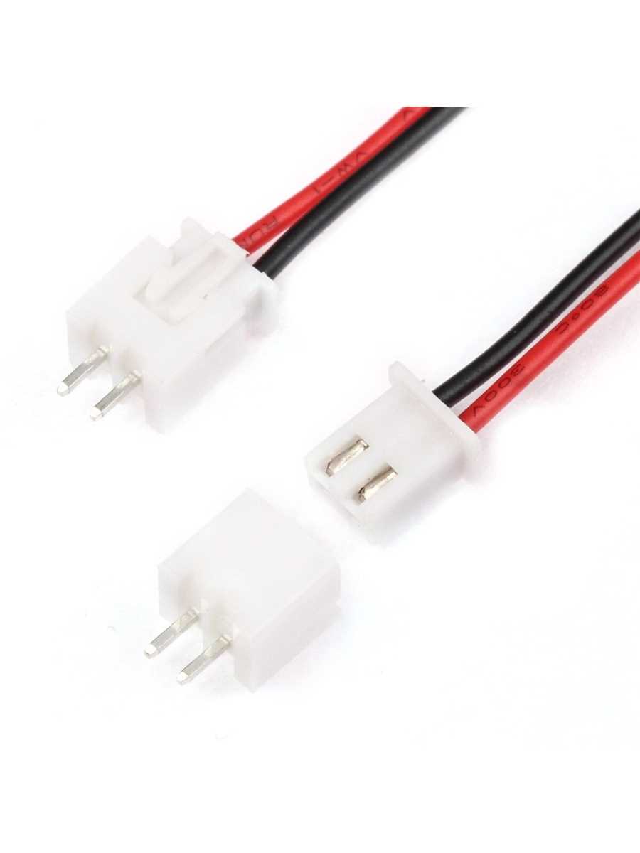
In the realm of electrical connections, comprehending the layout and directionality of pins is paramount for seamless integration and functionality. This section delves into the intricate nuances of pin configuration and orientation, shedding light on the pivotal aspects that dictate successful engagement and interoperability.
| Aspect | Explanation |
|---|---|
| Alignment | Ensuring the proper alignment of pins guarantees optimal electrical conductivity and prevents potential damage during insertion. |
| Positioning | Understanding the designated positions of pins within a connector aids in establishing secure and stable connections, fostering reliability in electronic systems. |
| Orientation | Correctly orienting pins according to specified guidelines ensures coherence between mating components, minimizing the risk of misalignment or reversed polarity. |
| Identification | Implementing effective methods for pin identification facilitates swift and accurate assembly, reducing troubleshooting time and enhancing overall efficiency. |
By grasping the intricacies of pin configuration and orientation, engineers and enthusiasts alike can navigate the intricacies of electrical connections with confidence and precision, propelling projects towards successful fruition.
Electrical Specifications and Ratings Explained

In this section, we delve into the intricacies of the electrical specifications and ratings pertinent to the discussed components. Understanding the electrical parameters is pivotal for ensuring optimal performance and safety in electrical systems. By elucidating these specifications, we aim to provide clarity on the functionality and limitations of the components in question.
Voltage Ratings
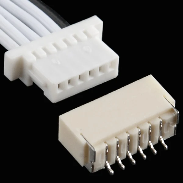
One of the fundamental aspects to consider is the voltage rating, which delineates the maximum allowable voltage that the component can withstand without succumbing to damage or malfunction. Voltage ratings are crucial for determining the compatibility and safety of the component within a given electrical circuit. It is imperative to adhere to the prescribed voltage ratings to prevent overloading or detrimental effects on the component.
Current Specifications
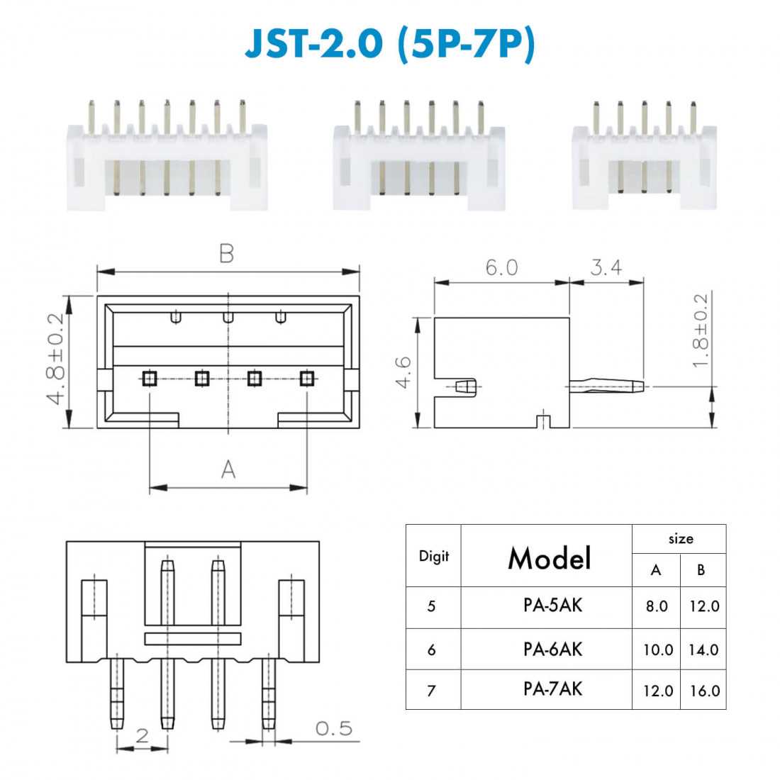
Another vital facet is the current specifications, which elucidate the maximum current that the component can handle without overheating or jeopardizing its integrity. Current specifications are pivotal for ensuring proper functionality and longevity of the component within an electrical system. Adhering to the specified current limits mitigates the risk of electrical failures and ensures optimal performance.
Interpreting Dimensional Drawings and Tolerances
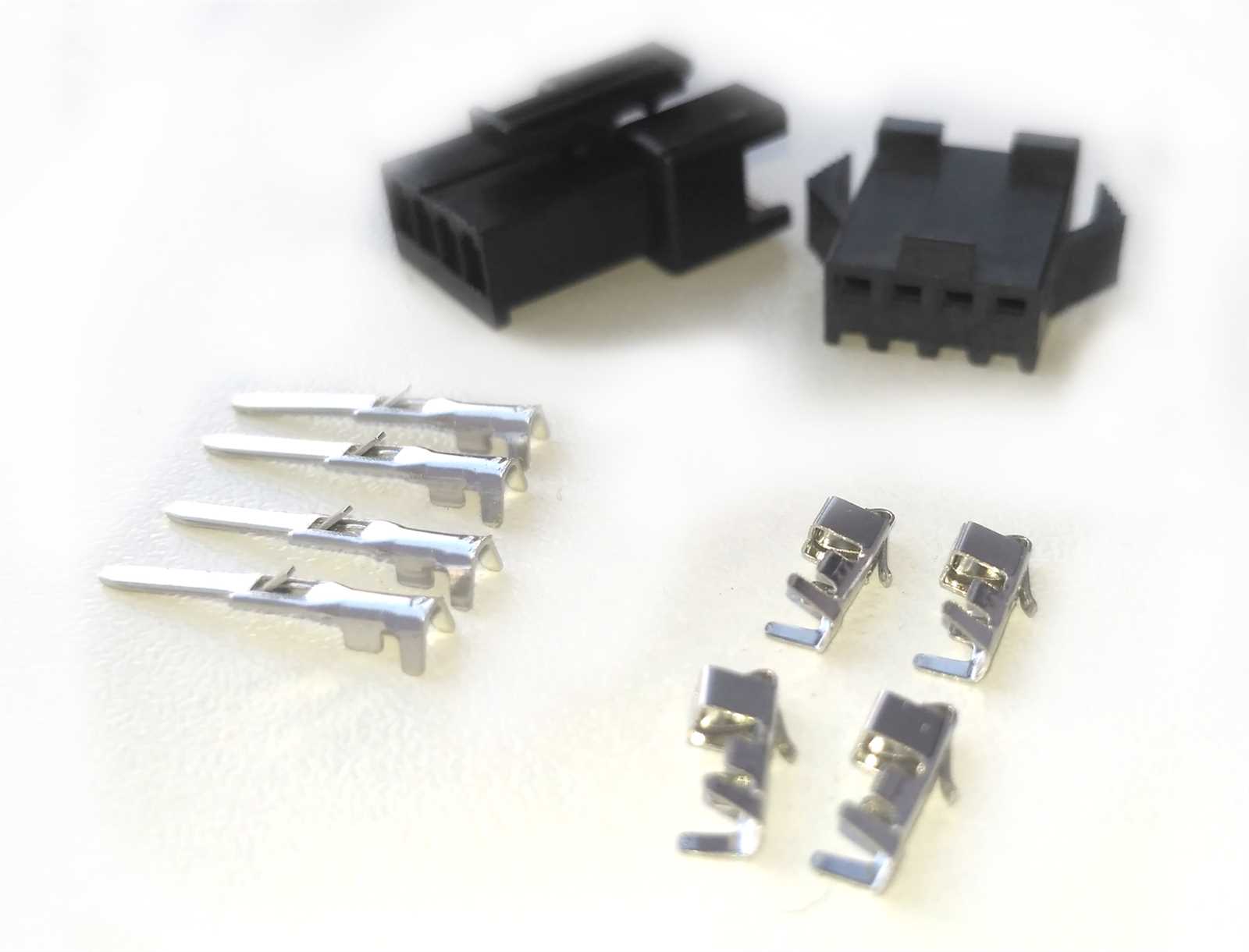
Understanding the intricacies of dimensional drawings and tolerances is pivotal in comprehending the specifications of electronic components. These blueprints serve as intricate maps, delineating the precise measurements and acceptable variations within a given component’s design. By delving into the nuances of these drawings, engineers and technicians glean invaluable insights into the form, fit, and function of the component in question.
The Language of Dimensional Drawings
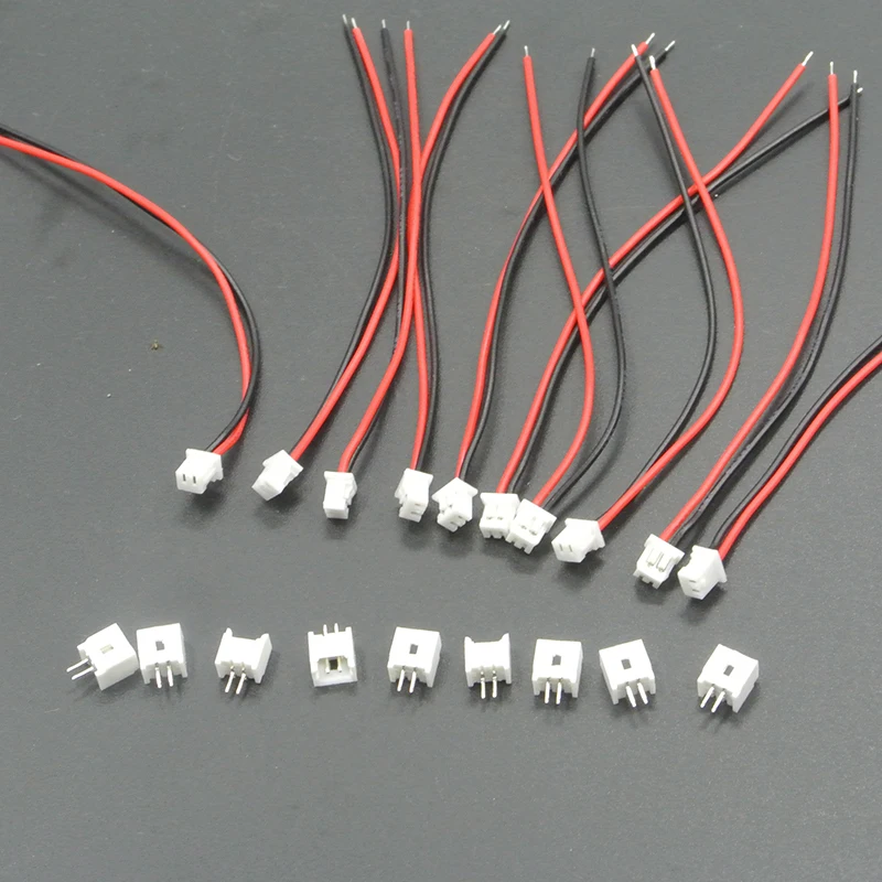
Dimensional drawings encapsulate a rich language of symbols and annotations, each carrying specific meanings that decode the geometric attributes of a component. From linear dimensions to geometric tolerances, these drawings elucidate the physical characteristics and spatial relationships critical for component integration and performance.
Deciphering Tolerances
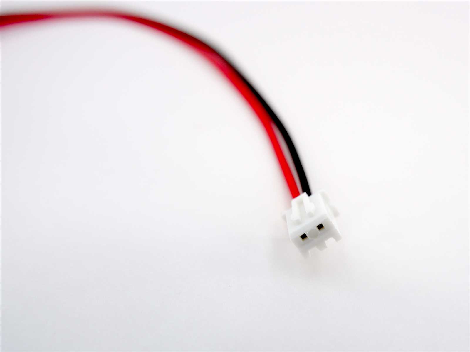
Tolerances delineate the permissible deviations from ideal dimensions, guiding manufacturers and assemblers in ensuring the functionality and compatibility of components. Understanding these tolerances is akin to navigating a spectrum of acceptable variability, where precision meets practicality in the realm of electronic assembly.
| Symbol | Meaning |
|---|---|
| ⌀ | Diameter |
| ± | Tolerance |
| □ | Squareness |
| ⊥ | Perpendicularity |