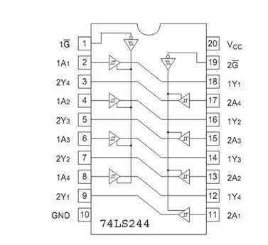
In the realm of electronic components, navigating through technical documentation is akin to deciphering a complex puzzle. These documents serve as maps, guiding engineers and enthusiasts through the intricate landscape of integrated circuits. Within this labyrinth of specifications and diagrams lies a wealth of information, offering insights into the functionality, performance, and application nuances of these electronic marvels.
Unlocking the intricacies of integrated circuit documentation requires a blend of analytical prowess and contextual understanding. It’s not merely a catalog of components, but rather a narrative detailing the inner workings of electronic systems. Each specification, each diagram, each notation contributes to the grand tapestry of knowledge, shedding light on the capabilities and limitations of the component in question.
Exploring these documents is akin to embarking on a journey through the corridors of innovation. It’s a voyage where clarity emerges from complexity, where understanding is forged through meticulous examination. Whether delving into the architecture of logic gates or scrutinizing timing diagrams, every detail holds significance, paving the way for informed design decisions and creative implementations.
The Fundamentals of Deciphering a 74LS82 Documentation
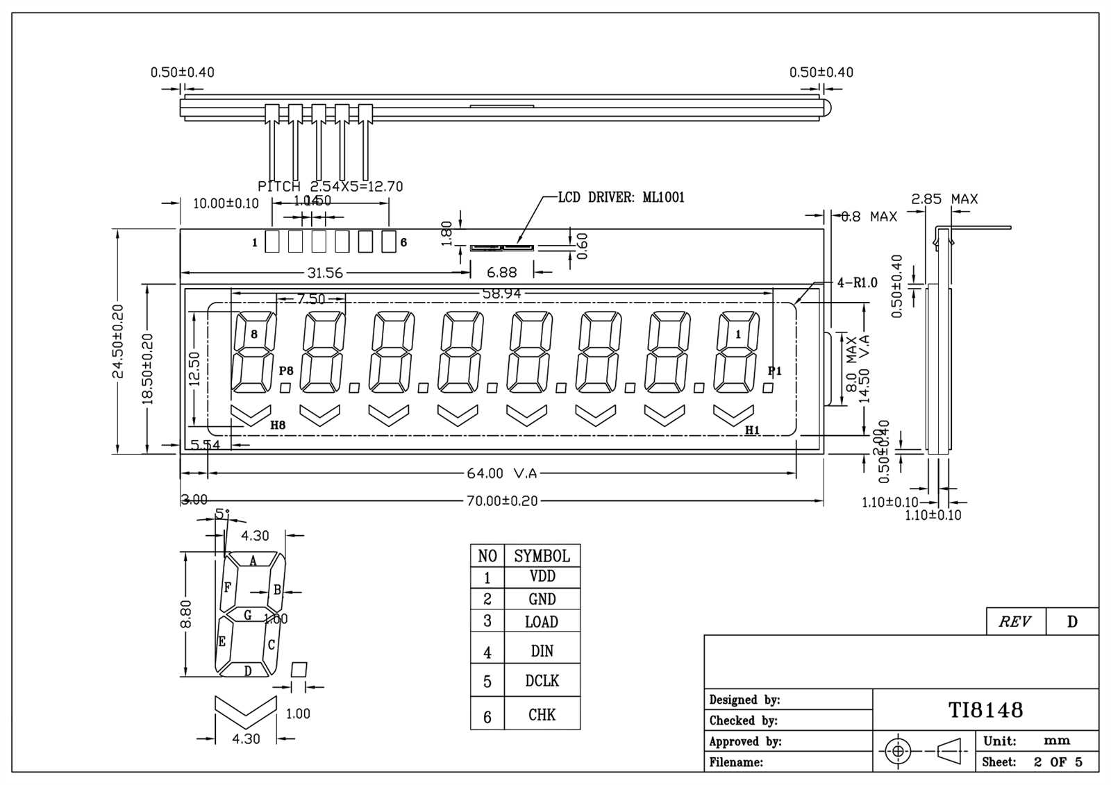
Embarking on the journey of comprehending the intricacies encapsulated within a technical documentation akin to the 74LS82 involves delving into a realm where abstraction converges with practicality. Within these pages lies a roadmap, a key to unlocking the potential and functionality of a component vital to electronic systems. By dissecting its contents, one can unravel the essence of its operation, paving the path towards informed decision-making and efficient utilization.
Exploring the Blueprint: At its core, this endeavor entails deciphering a blueprint, a schematic of sorts, detailing the inner workings of a foundational building block in electronic circuits. It’s akin to navigating through the labyrinth of electrical pathways, where each line, each symbol holds significance, painting a holistic picture of functionality and interconnection.
Decoding the Language: Embedded within the pages of this documentation is a language unique unto itself. From truth tables to timing diagrams, each section speaks volumes, conveying crucial information regarding input-output relationships, operational parameters, and performance metrics. Mastery of this lexicon is paramount, akin to grasping the dialect of a specialized community.
Unveiling Operational Insights: Beyond the surface lies a treasure trove of operational insights waiting to be unearthed. From logical operations to propagation delays, every nugget of information serves as a beacon guiding the design, implementation, and troubleshooting phases of electronic systems. It’s a narrative woven with precision and clarity, offering a roadmap towards efficient utilization and optimization.
Charting a Course: Ultimately, the journey of understanding a 74LS82 documentation transcends mere comprehension; it’s a voyage towards empowerment and innovation. Armed with knowledge and insight, engineers and enthusiasts alike can chart a course towards harnessing the full potential of this enigmatic component, steering towards realms of creativity and functionality yet to be explored.
Exploring Key Features and Specifications
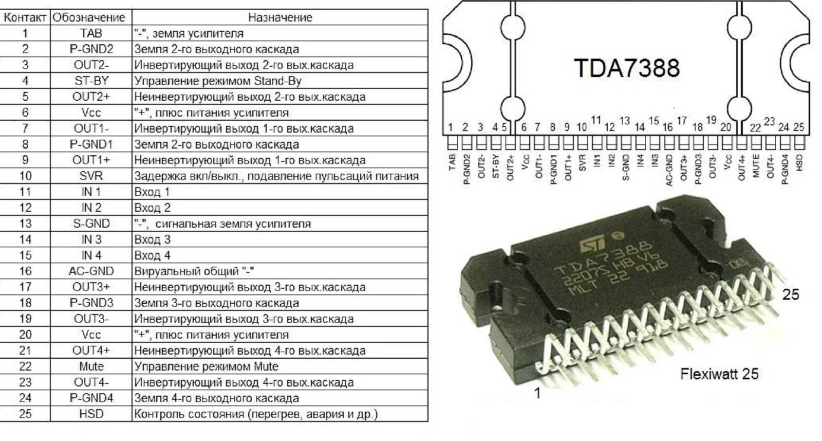
In this section, we delve into the essential characteristics and technical specifications of the component under scrutiny. Through a detailed examination, we aim to unravel the distinctive attributes and functionalities that distinguish this electronic module in the realm of integrated circuits.
1. Performance Metrics
Let’s begin by dissecting the performance metrics that underscore the operational efficiency and efficacy of this component. From speed considerations to power consumption, we unravel the intricate details that contribute to its overall functionality.
- Operating Speed: Analyzing the pace at which data processing occurs, highlighting its impact on overall system performance.
- Power Consumption: Evaluating energy efficiency and power requirements, crucial for optimizing resource utilization.
- Noise Immunity: Assessing the component’s resilience against external interference, ensuring reliable operation in varied environmental conditions.
2. Architectural Insights
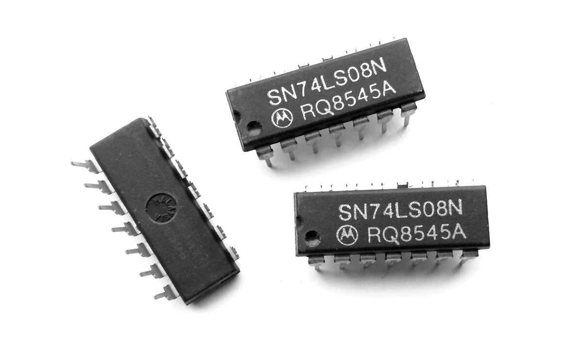
Delving deeper, we explore the architectural nuances that define the core structure and design principles of this integrated circuit. From logical arrangements to connectivity options, we unveil the underlying framework that enables seamless integration within electronic systems.
- Logic Configuration: Unraveling the logical architecture that governs data processing and decision-making within the component.
- Input/Output Interfaces: Examining the interface compatibility and connectivity options, pivotal for interoperability with external devices.
- Functional Units: Dissecting the constituent functional blocks and their respective roles in achieving desired system behavior.
Through this comprehensive exploration, we aim to provide a holistic understanding of the key features and specifications that define the essence of this electronic component.
Understanding Pin Configuration and Functionality
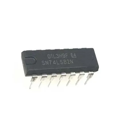
In this section, we delve into comprehending the intricacies of pin arrangement and operational aspects of the device in focus. By dissecting the pin configuration and elucidating its functionality, we aim to provide a comprehensive understanding of its operational framework.
Firstly, let’s explore the physical layout of the component, deciphering the significance of each pin’s placement. By examining the relative positioning and interconnection of pins, we gain insights into the structural design and operational flow.
Subsequently, we embark on deciphering the functionality associated with each pin. Through systematic analysis, we elucidate the role of individual pins in contributing to the overall functionality of the device. This entails discerning input and output functionalities, as well as any specialized roles specific pins may fulfill.
- Pin Identification: Unraveling the unique identifiers assigned to each pin, facilitating seamless integration and troubleshooting processes.
- Input Functionality: Investigating the input pins and their respective roles in receiving and processing external signals or data.
- Output Functionality: Examining the output pins and their functions in transmitting processed information or signals to external components.
- Specialized Pins: Delving into any specialized pins that may possess distinct functionalities or contribute to specific operations within the device.
By elucidating the intricacies of pin configuration and functionality, we aim to empower users with the knowledge necessary for proficient utilization and integration of the component into diverse electronic systems.
Interpreting Electrical Characteristics and Timing Diagrams
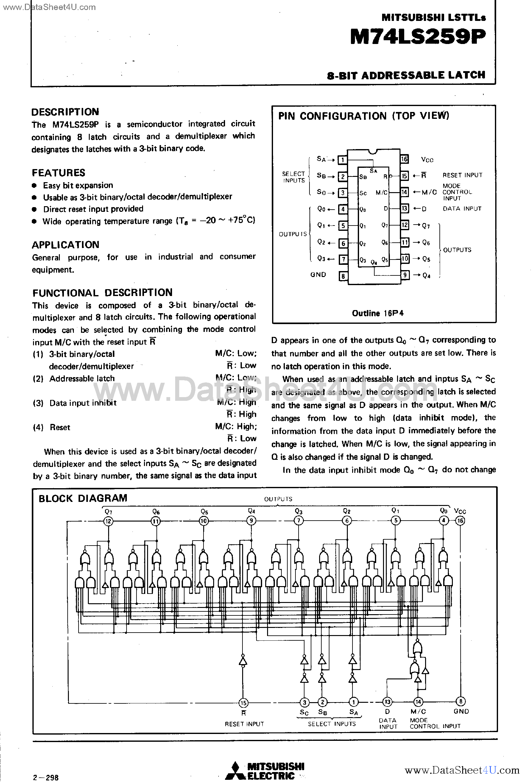
Understanding the intricacies of electronic components involves delving into the nuances of their electrical behaviors and the graphical representations that depict these dynamics. In this section, we explore the fundamental concepts behind interpreting electrical characteristics and timing diagrams, shedding light on the essential insights they offer into the performance and functionality of integrated circuits.
Electrical Characteristics
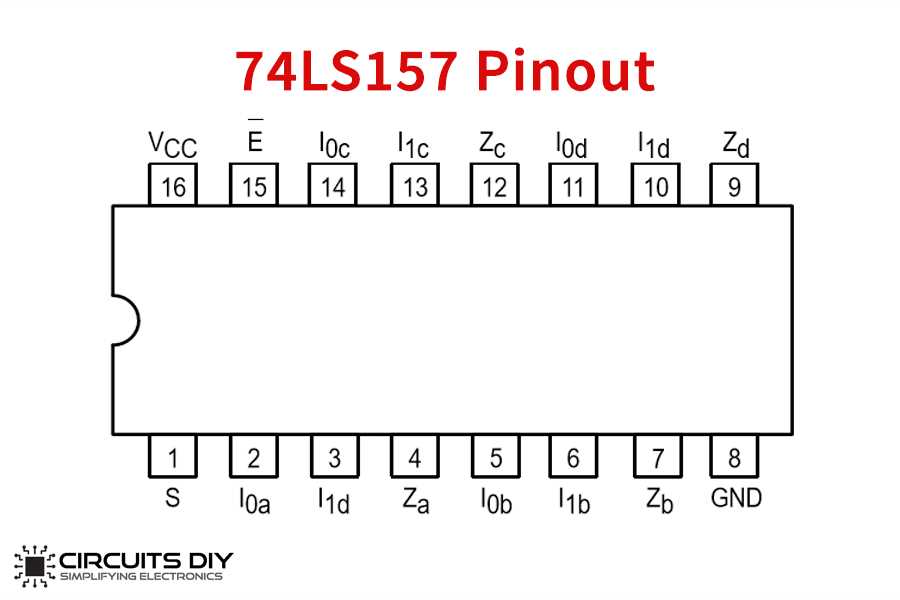
Before delving into the specifics of timing diagrams, it’s crucial to grasp the significance of electrical characteristics. These parameters encapsulate the essential traits of a component’s behavior within an electrical circuit, encompassing factors such as voltage levels, current requirements, and signal propagation characteristics. By comprehending these attributes, engineers can assess how a component interacts within a circuit and optimize its integration for desired performance outcomes.
Timing Diagrams: Insights into Component Behavior
Timing diagrams serve as graphical representations of the temporal relationships between input and output signals within an electronic system. These diagrams offer valuable insights into the dynamic behavior of integrated circuits, illustrating phenomena such as signal propagation delays, setup and hold times, and timing constraints. By analyzing timing diagrams, engineers can pinpoint potential issues related to signal integrity, timing violations, and overall system performance, facilitating informed design decisions and optimizations.