Understanding the intricate details of electronic components involves delving into the specifications and characteristics that define their functionality. In the realm of digital electronics, these specifications serve as guiding principles, shaping the design and implementation of various circuits. Among these components, one finds a plethora of integrated circuits offering diverse functionalities, each with its own set of specifications elucidating its performance and capabilities.
Exploring the specifications of a particular integrated circuit unveils a roadmap detailing its behavior under different operating conditions. These specifications encapsulate crucial parameters such as voltage requirements, input/output characteristics, and operational modes, offering engineers valuable insights into its usage and integration within electronic systems.
Embarking on a journey through the specifications of an integrated circuit opens avenues for understanding its intricacies and leveraging its features effectively. Through careful analysis and interpretation, engineers decipher the nuances embedded within these specifications, paving the way for informed decision-making and optimized circuit designs.
Understanding the Operational Overview of 74HC155 Documentation
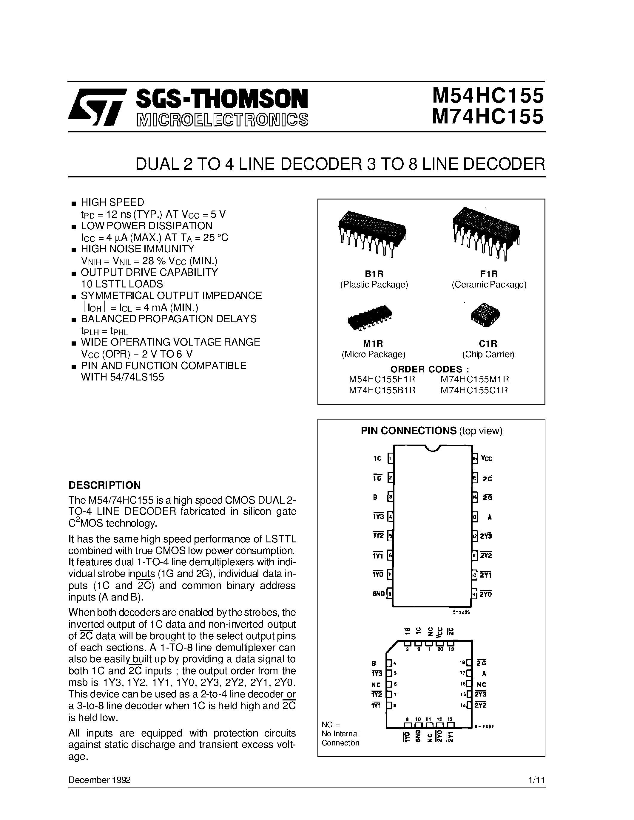
In delving into the intricacies of the resource at hand, it’s imperative to grasp the essence of its operational framework. Within the expansive realm of electronic components, comprehending the functional blueprint of this particular document serves as a foundational step towards harnessing its potential.
Exploring this informational dossier involves navigating through a labyrinth of specifications, configurations, and guidelines. Within its pages lie the key to unraveling the intricacies of a critical electronic component, offering insights into its capabilities and potential applications.
- Unveiling the architectural nuances
- Deciphering the performance metrics
- Interpreting the operational guidelines
Through a meticulous examination, one can unlock a wealth of knowledge embedded within this comprehensive document. Understanding the functionality encapsulated within its pages empowers engineers and enthusiasts alike to harness the full potential of the component it represents.
Exploring the Key Features and Specifications

In this section, we delve into the essential characteristics and technical details of the component under scrutiny, shedding light on its functionality and performance without explicitly referencing its specific nomenclature or documentation. Our exploration aims to provide a comprehensive understanding of the component’s capabilities and specifications, offering insights into its operational parameters and potential applications.
Performance Metrics

- Functional Capabilities
- Operational Efficiency
- Data Handling Capacity
The performance metrics of interest encompass a spectrum of factors contributing to the component’s overall functionality and utility. By analyzing its functional capabilities, operational efficiency, and data handling capacity, we gain a nuanced understanding of its operational prowess and potential limitations, paving the way for informed decision-making in its utilization.
Technical Specifications
- Input and Output Characteristics
- Power Requirements
- Operating Temperature Range
Delving deeper into the technical realm, we explore the intricate specifications defining the component’s behavior and compatibility within diverse electronic environments. From input and output characteristics to power requirements and operating temperature ranges, each specification plays a crucial role in delineating the component’s operational boundaries and suitability for specific applications.
Analyzing Application Circuits and Diagrams
Delving into the intricacies of electronic configurations and visual representations thereof forms the crux of this section. We embark on a journey through the labyrinth of application circuits and diagrams, deciphering their structures, functions, and interconnections. Through meticulous examination, we unravel the underlying principles driving circuit operation and explore the symbiotic relationship between theoretical concepts and practical applications.
Deciphering Circuit Configurations
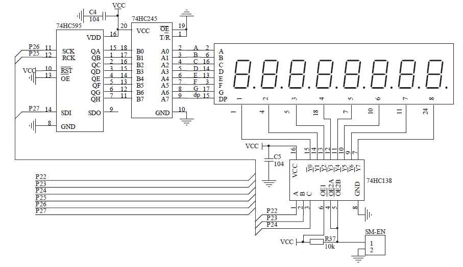
Within the realm of electronic schematics lie a myriad of configurations, each tailored to fulfill specific functionalities. By dissecting these arrangements, we uncover the synergy between discrete components and integrated circuits, discerning the roles they play in achieving desired outcomes. From amplifiers to oscillators, each circuit configuration boasts its own unique attributes, contributing to the vast tapestry of electronic design.
Interpreting Diagrammatic Representations

Diagrams serve as visual blueprints, encapsulating the essence of circuit functionality in a concise and comprehensible format. Through meticulous analysis, we decode the symbolism embedded within these diagrams, elucidating the flow of signals and the interaction of components. By bridging the gap between abstract concepts and tangible implementations, we gain insight into the underlying mechanisms governing electronic systems.
Interpreting Electrical Characteristics and Timing Diagrams
In the realm of electronic components, understanding the intricacies of electrical characteristics and timing diagrams is paramount for effective utilization. These elements serve as a blueprint, guiding engineers and enthusiasts alike in comprehending the behavior and performance of various circuits and devices. Through careful analysis and interpretation, one can unveil crucial insights into signal propagation, voltage levels, timing requirements, and operational limits.
Deciphering Electrical Characteristics
Electrical characteristics encapsulate a wealth of information pertaining to the behavior of a component within an electrical system. These specifications encompass parameters such as input/output voltage levels, current ratings, propagation delays, and power dissipation. By delving into these details, one can ascertain the compatibility of a component with a given application, ensuring optimal performance and reliability.
Unraveling Timing Diagrams
Timing diagrams provide a visual representation of the temporal relationships between various signals within a circuit. Through these graphical depictions, engineers can elucidate critical aspects such as clock frequencies, setup and hold times, pulse widths, and propagation delays. By meticulously analyzing timing diagrams, one can fine-tune circuit designs, mitigate timing hazards, and optimize overall system performance.
| Electrical Characteristic | Description |
|---|---|
| Input Voltage | The range of acceptable voltage levels at the input of the component. |
| Output Current | The maximum current that can be drawn from the output without causing damage. |
| Propagation Delay | The time taken for a signal to propagate through the component. |
| Power Dissipation | The amount of power dissipated by the component during operation. |
| Timing Parameter | Description |
|---|---|
| Clock Frequency | The frequency at which the circuit operates, typically expressed in hertz (Hz). |
| Setup Time | The minimum time required for a signal to be stable before the clock edge. |
| Hold Time | The minimum time required for a signal to remain stable after the clock edge. |
| Pulse Width | The duration of time during which a signal remains at a logic high or low level. |