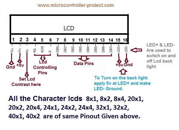
Have you ever wondered how modern electronic devices manage to display information with such precision and clarity? Behind the scenes of these sleek gadgets lies a complex network of interconnected components, each playing a crucial role in bringing the digital world to life. In this article, we dive into the intriguing realm of the 20×2 LCD display pinout datasheet, uncovering the secrets behind its functionality and exploring the possibilities it presents.
Unleashing the Power of Connectivity
The 20×2 LCD display pinout datasheet serves as a roadmap, guiding engineers and enthusiasts alike to harness the full potential of this powerful electronic component. By providing detailed information about the arrangement and functions of each pin, it serves as a valuable resource for anyone looking to understand and utilize the capabilities of the 20×2 LCD display.
Embarking on a Journey of Discovery
With an array of pins at its disposal, the 20×2 LCD display opens up a world of possibilities. By following the guidance of the pinout datasheet, users can uncover the inner workings of this component and unlock its full potential. From understanding the power and ground connections to deciphering the data and control pins, this datasheet acts as a trusted companion on the journey of discovery into the realm of LCD displays.
Innovation and Creativity Unleashed
Armed with the knowledge provided by the 20×2 LCD display pinout datasheet, engineers and tinkerers can push the boundaries of what is possible. Whether it’s building a smart home system, designing an engaging user interface, or creating interactive art installations, the versatility of the 20×2 LCD display allows for endless opportunities for innovation and creativity.
Understanding the Wiring Diagram of a 20×2 Liquid Crystal Display
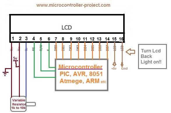
The purpose of this section is to provide a comprehensive understanding of the pin configuration and wiring diagram of a popular liquid crystal display (LCD) with dimensions of 20×2 characters. By delving into the intricate details of the pinout, users will gain insight into how to properly interface with this component and leverage its capabilities in various electronic projects.
Exploring the connectivity of the 20×2 LCD display involves comprehending the arrangement and function of its numerous pins, which can be visualized using a concise table. This table will outline each pin’s name and significance, thereby enabling the reader to establish a clear mental map of the display’s internal circuitry. Understanding how the pins interact with one another is essential for correctly wiring the LCD display to a microcontroller or other electronic devices.
| Pin Name | Description |
|---|---|
| VCC | The power supply voltage input pin |
| GND | The ground (0V) reference pin |
| RS | The register select pin for choosing between data and command modes |
| R/W | The read/write pin for selecting between read and write operations |
| E | The enable pin for initiating data transfers |
| D0-D7 | The 8-bit data pins for sending and receiving data |
| LED+ | The positive terminal of the backlight LED |
| LED- | The negative terminal of the backlight LED |
Once the purpose and functionality of each pin have been established, a clear understanding of the wiring diagram can be formed. By identifying the specific pins required for power, data, and backlight control, users will be able to plan their circuit layout accordingly and ensure a successful connection. It is crucial to double-check the pinout against the datasheet provided by the manufacturer to avoid any wiring mistakes that may result in improper functioning of the LCD display.
By having a solid grasp of the pinout and wiring diagram of a 20×2 LCD display, users can confidently integrate this component into their projects and make the most of its versatile features. Whether used in embedded systems, robotics, or other applications, this understanding will enable users to harness the full potential of the LCD display and achieve their desired functionality.
The Basics: Pin Configuration
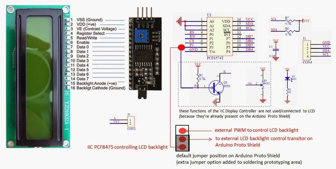
In this section, we will explore the fundamental aspects of the pin configuration for a 20×2 LCD display. Understanding the pin configuration is crucial for properly connecting and utilizing the display in various applications. By comprehending the layout and purpose of each pin, you will be able to effectively communicate with the LCD and exploit its functionalities.
The pin configuration of the LCD display determines the way it interacts with other components in a circuit. Each pin serves a specific role, enabling the exchange of data, control signals, and power supply. By following the pinout diagram, you can ensure a seamless integration of the LCD display into your project, allowing for accurate and efficient data display.
One of the essential pins on the LCD display is the power supply pin. It provides the necessary voltage for the display to function correctly. By connecting this pin to a reliable power source, you guarantee that the LCD display receives the required power to operate optimally.
Another crucial pin is the ground pin, which establishes an electrical connection between the display and the ground reference of the system. It ensures proper signaling and reduces noise interference, which is particularly essential in sensitive applications where accurate data representation is crucial.
The data pins, also called digital pins, play a significant role in transmitting data from the microcontroller to the LCD display. These pins are responsible for carrying the binary information that represents characters and symbols to be displayed on the screen. By configuring these pins correctly, you can seamlessly convey data and enable the LCD to portray the desired information.
The control pins, on the other hand, manage the overall operation of the LCD display. These pins include the enable pin, which activates the display by allowing data to be written or read, and the register select pin, which determines whether the incoming data is a command or character code. By effectively handling these control pins, you have full control over the workflow and functionality of the LCD display.
Lastly, there are auxiliary pins that provide additional functionalities for the LCD display, such as backlight control or contrast adjustment. These pins allow for customization and optimization of the display’s appearance and functionality to meet specific project requirements.
In conclusion, understanding the pin configuration is vital for utilizing the full potential of a 20×2 LCD display. By comprehending the purpose and function of each pin, you can create an optimal connection and exploit the display’s capabilities effectively.
Exploring the Datasheet: Functionality and Features
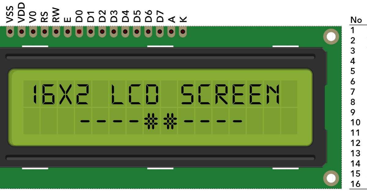
In this section, we will delve into the comprehensive datasheet that provides detailed information on the functionality and features of a specific electronic component. By understanding the contents of the datasheet, engineers and hobbyists can gain insights into the capabilities and potential applications of the component.
Overview of Functionality
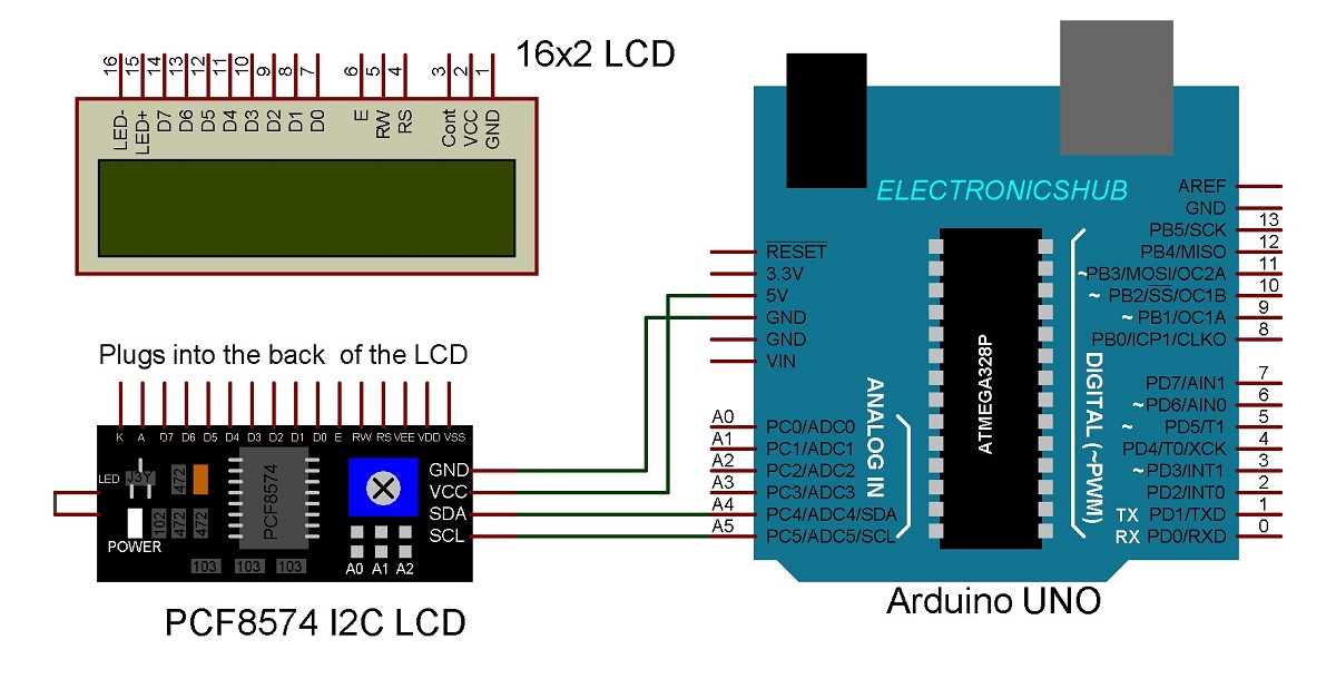
The datasheet offers a comprehensive overview of the functional capabilities of the electronic component, providing valuable insights into its performance characteristics and operational parameters. It provides detailed information on the various functions and operations that can be performed using the component, shedding light on how it can be used in combination with other electronic devices.
Features and Specifications
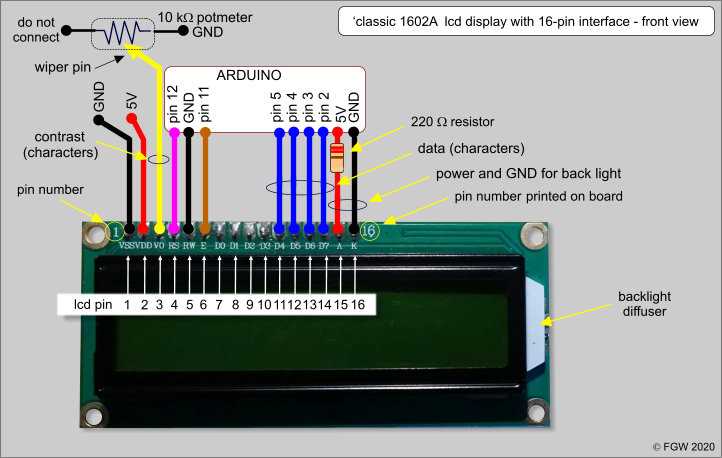
One of the key sections of the datasheet focuses on the component’s features and specifications. This section provides a detailed breakdown of various attributes such as voltage range, current consumption, operating temperature, and input/output pins. By studying this information, engineers can evaluate whether the component satisfies the requirements of their specific application.
| Feature | Description |
|---|---|
| Input Voltage Range | Defines the acceptable range of input voltage for the component. |
| Current Consumption | Specifies the amount of current the component draws during operation. |
| Operating Temperature | Indicates the range of temperatures within which the component can function reliably. |
| Input/Output Pins | Lists and describes the pins used for input and output connections. |
By understanding the features and specifications, engineers can make informed decisions about the component’s suitability for their intended applications, ensuring compatibility and optimal performance.
To effectively explore the datasheet, it is essential to examine each section carefully, cross-referencing the information to gain a comprehensive understanding of the component’s functionality and features. This in-depth analysis is crucial for successful integration of the component into various electronic systems and designs.