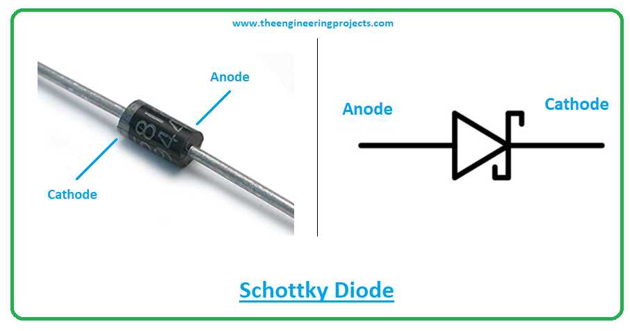
Embark on a journey through the intricate tapestry of electronic components, where each component serves as a pillar in the foundation of modern technology. Within this cosmic expanse of circuits and currents, lies a realm where the minuscule yet mighty entities known as semiconductor junctions reign supreme.
Today, we set our gaze upon a remarkable emissary of this realm, a guardian of electrical flow and harbinger of directional current–known not by name, but by its code: the enigmatic 1N5403.
Delve into the annals of its manifesto, a document that encapsulates its essence, unveiling its mysteries and unveiling the secrets encoded within its lines. Join us as we decode the blueprints of this silent sentinel, navigating through its symbolic language to uncover the symphony of potentialities it holds within.
Understanding the Specifications of the 1N5403 Rectifier
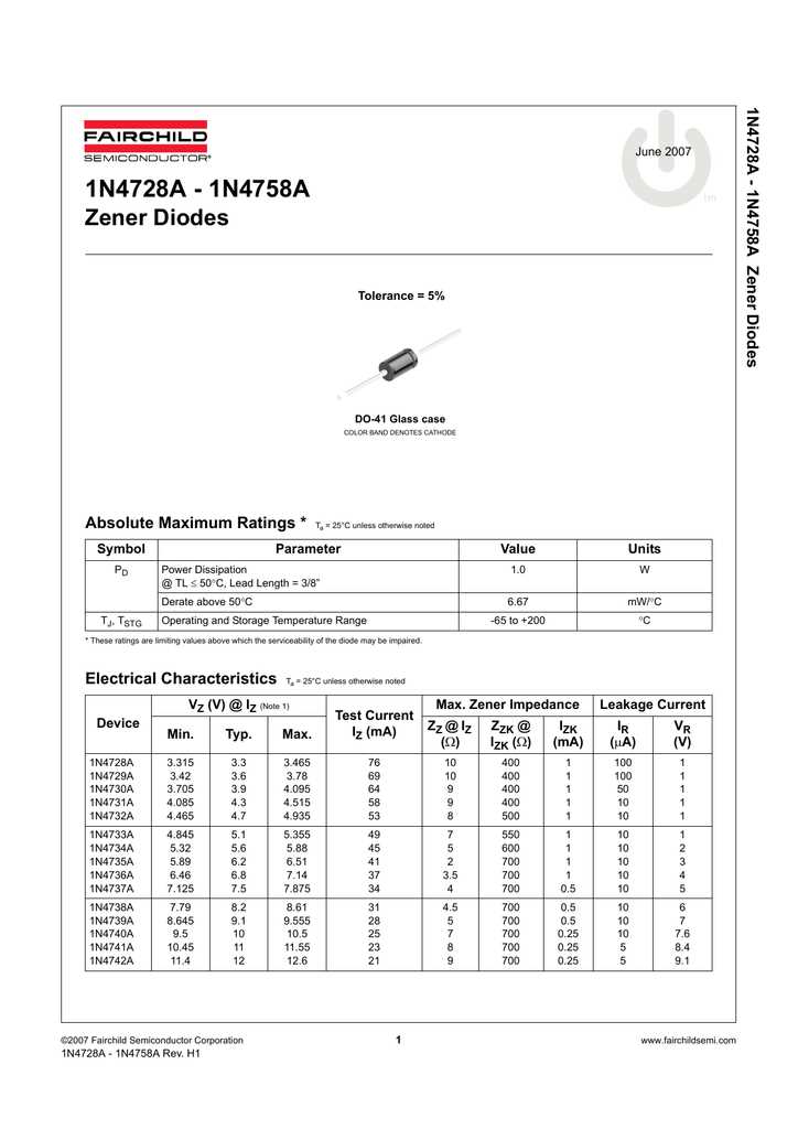
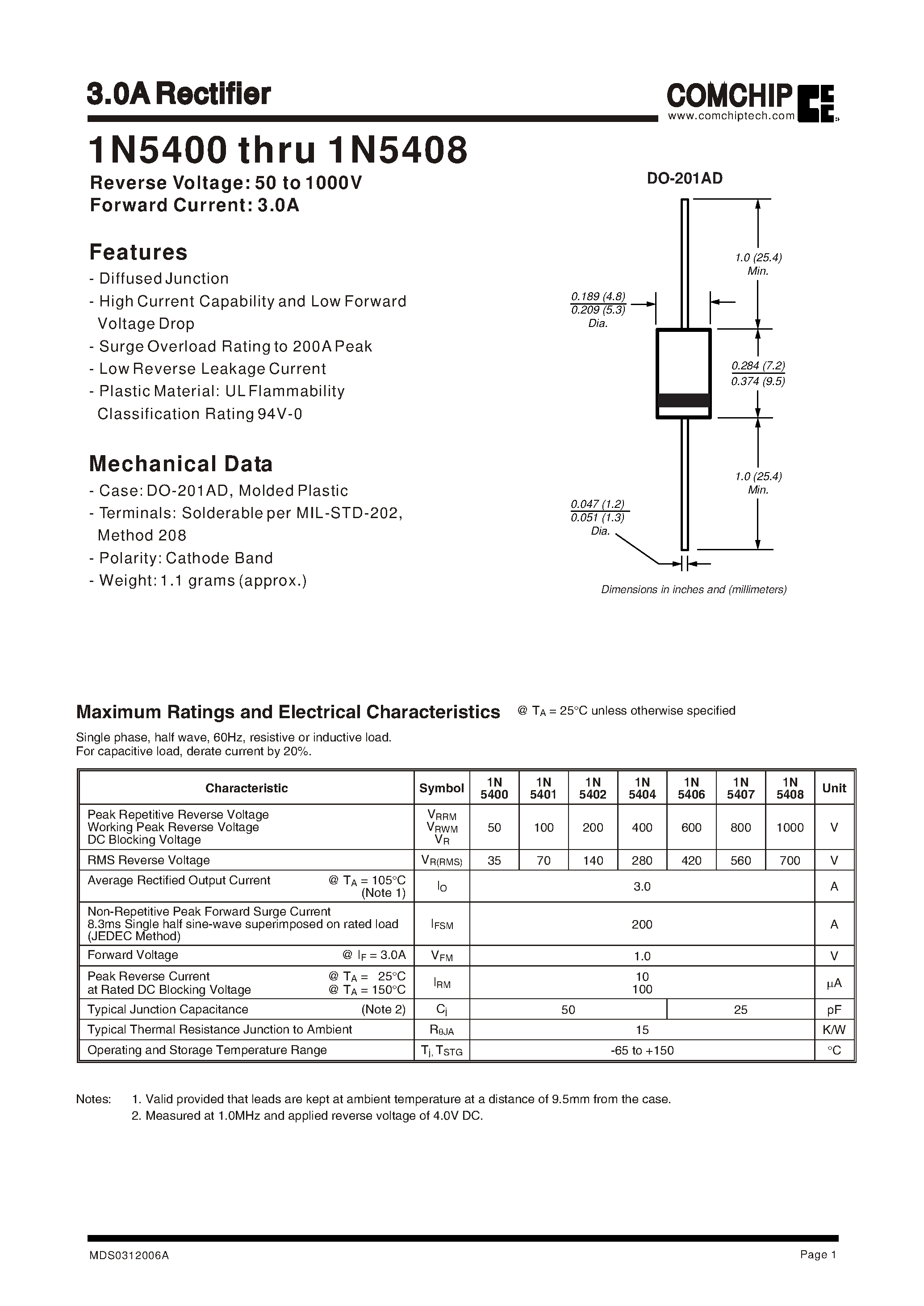
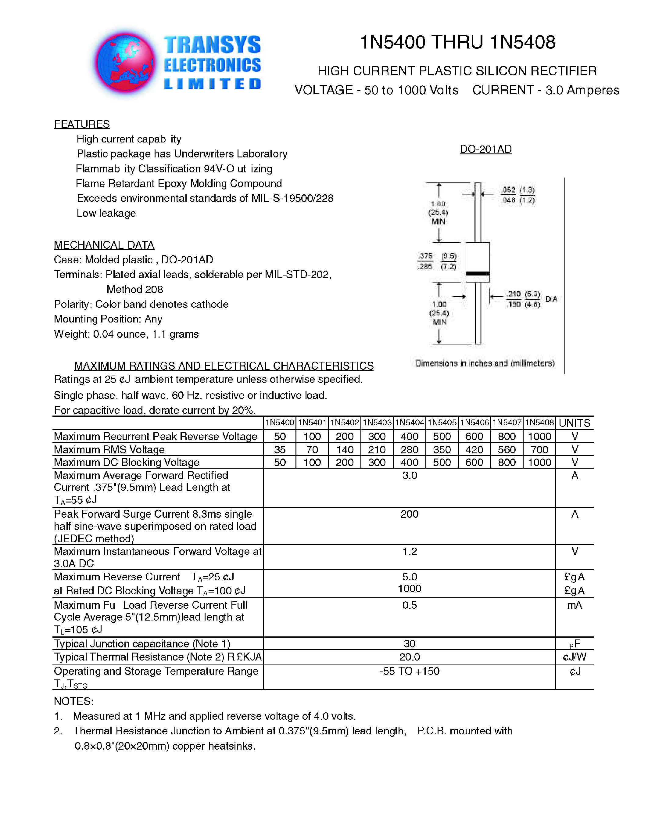
When delving into the intricacies of electronic components, it’s essential to grasp the detailed documentation accompanying each device. In the realm of rectifiers, a comprehensive comprehension of the provided specifications serves as a guiding beacon for engineers and hobbyists alike. Within the labyrinth of technical jargon and numerical values lies a wealth of information vital for proper utilization and integration of the rectifier into electronic circuits.
Deciphering Electrical Characteristics
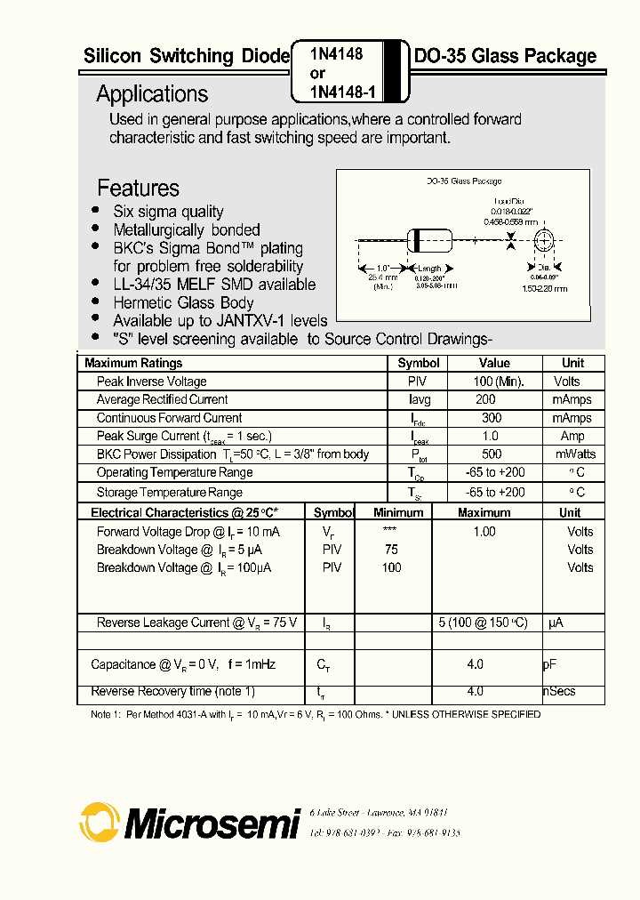
Embedded within the datasheet are a myriad of electrical characteristics delineating the behavior of the rectifier under various conditions. These encompass parameters such as forward voltage, reverse voltage, forward current, and reverse current, each shedding light on the rectifier’s operational limits and performance thresholds.
Exploring Mechanical Dimensions and Packaging
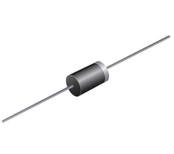
Beyond the realm of electrical properties, the datasheet elucidates the physical attributes of the rectifier, elucidating its mechanical dimensions and packaging. Insight into factors like lead length, terminal configuration, and mounting orientation aids in the seamless integration of the rectifier within diverse circuit layouts, ensuring optimal functionality and reliability.
Understanding these specifications not only facilitates informed decision-making during the design phase but also empowers troubleshooters to pinpoint potential issues and devise effective solutions. Thus, delving into the intricacies of the 1N5403 rectifier datasheet is an indispensable endeavor for any discerning electronics enthusiast.
Key Specifications Explained
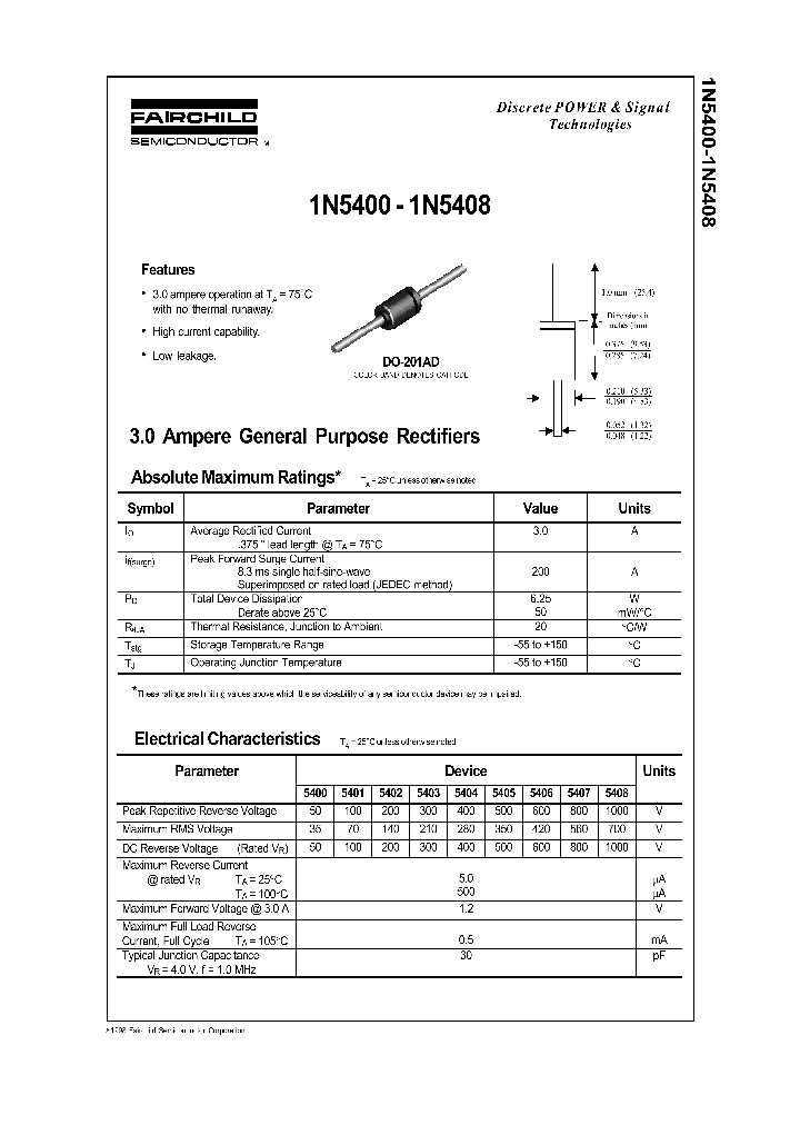
In this section, we delve into the critical parameters that define the performance and functionality of the component under scrutiny. Understanding these key specifications is paramount for grasping the operational characteristics and potential applications of the device.
Forward Voltage Drop
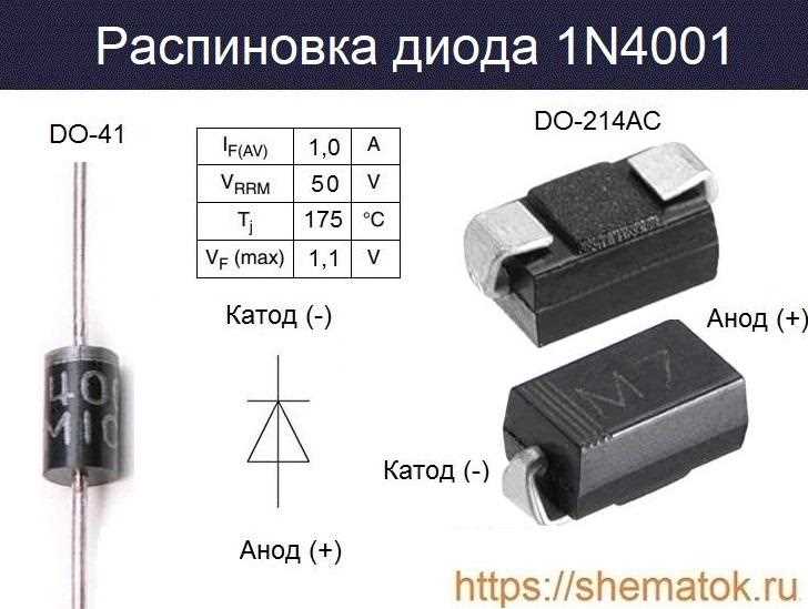
The forward voltage drop, often referred to as the diode’s conducting voltage, signifies the voltage required to allow current flow through the diode in the forward direction. It is a fundamental parameter that influences the efficiency of the diode in converting alternating current (AC) to direct current (DC).
Maximum Reverse Voltage
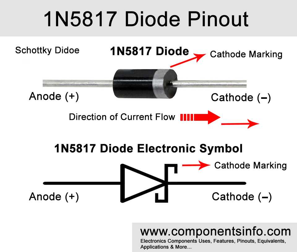
Also known as the reverse breakdown voltage, this specification represents the maximum voltage that can be applied across the diode in the reverse direction without causing a significant reverse current to flow. Understanding this parameter is crucial for ensuring the diode’s reliability and longevity in circuit applications.
- Reverse Voltage: The reverse voltage capability is a pivotal consideration, especially in rectifier and power supply designs where the diode is subjected to varying voltage conditions.
- Forward Current Rating: This specification denotes the maximum continuous forward current that the diode can safely conduct without exceeding its thermal limits.
- Reverse Recovery Time: The reverse recovery time characterizes the duration it takes for the diode to transition from the conducting state to the non-conducting state when the polarity of the applied voltage changes abruptly.
By comprehending these key specifications, designers and engineers can make informed decisions regarding the suitability of the diode for specific applications and ensure optimal performance within their circuits.
Application Notes and Circuit Examples
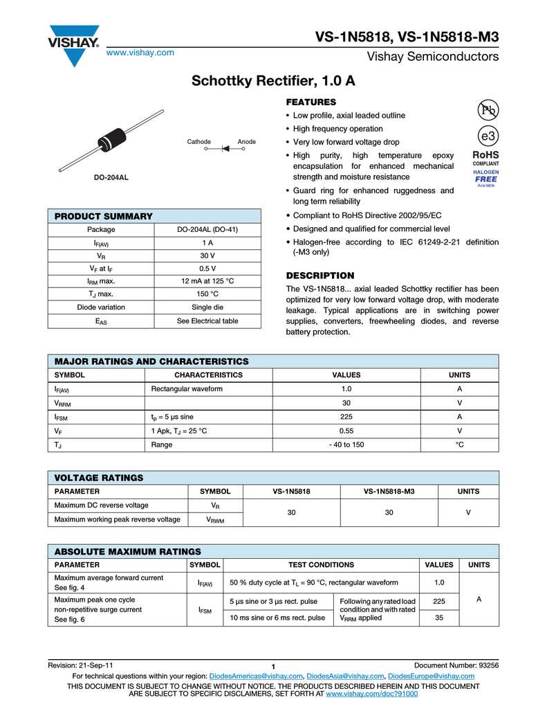
In this section, we delve into practical insights and illustrative instances showcasing the versatility and efficacy of the component under discussion. Through a variety of application notes and circuit examples, we illuminate the diverse scenarios where this electronic element can be employed to enhance functionality, ensure stability, or regulate electrical currents. From basic configurations to advanced setups, these real-world cases serve as invaluable guides for both novices and seasoned professionals in the realm of electronics.
- Exploring Fundamental Circuit Configurations
- Understanding Voltage Regulation Techniques
- Utilizing the Component in Power Supply Designs
- Enhancing Circuit Protection with Innovative Strategies
Each example encapsulates a distinct facet of the component’s utility, shedding light on its role within intricate circuits and highlighting best practices for optimal performance. Whether it’s safeguarding sensitive electronics from voltage spikes or facilitating seamless power delivery in demanding applications, the versatility of this component is underscored through practical demonstrations and insightful commentary.
Troubleshooting and Common FAQs
In this section, we delve into resolving issues and answering common questions that may arise when working with this particular component. Whether you’re facing unexpected behaviors or seeking clarity on its functionalities, the following information aims to provide clarity and guidance.
Common Issues and Solutions
Problem: The component is heating up excessively during operation.
Solution: Excessive heat generation can be attributed to several factors such as overloading, improper mounting, or inadequate ventilation. Check the current passing through the component and ensure it’s within the specified limits. Verify the mounting technique and ensure proper heat dissipation mechanisms are in place. Additionally, evaluate the surrounding environment for adequate airflow.
Frequently Asked Questions
Q: What is the maximum voltage this component can handle?
A: The component’s maximum voltage rating is crucial for its proper operation and longevity. Refer to the datasheet for the specific maximum voltage rating. Exceeding this voltage may lead to component failure or damage.
Q: How can I test if the component is functioning correctly?
A: Testing the component involves various methods depending on its application. Using a multimeter to check for continuity, forward voltage drop, and reverse leakage current can help verify its functionality. Additionally, subjecting the component to its rated conditions and monitoring its performance can provide further assurance.